

MY1B - SMC
MY1B - SMC
MY1B - SMC
- No tags were found...

You also want an ePaper? Increase the reach of your titles
YUMPU automatically turns print PDFs into web optimized ePapers that Google loves.
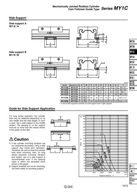
Mechanically Jointed Rodless CylinderCam Follower Guide TypeSeries MY1CSide SupportSide support AMY-SA2 x øGCDAB2 x øHFE<strong>MY1B</strong>MY1MSide support BMY-SBMY1CMY1H2 x JMY1HTMY1WCDABEMY2CMY2HModelMY-S16 ABMY-S20 ABMY-S25 ABMY-S32 ABApplicable bore sizeMY1C16MY1C20MY1C25MY1C32A616781100B71.679.695118C15253545D26385064E4.96.4811.7F3456G6.589.511MY-S40 ABMY1C40 120 142MY1C50 142 16455 80 14.8 8.5 14MY-S63 AB MY1C63 172 202 70 100 18.3 10.5 17.5∗ A set of side supports consists of a left support and a right support.H3.44.55.56.6911.5(mm)JM4 x 0.7M5 x 0.8M6 x 1M8 x 1.25M10 x 1.5M12 x 1.75MY3AMY3BMY3MGuide for Side Support ApplicationFor long stroke operation, the cylindertube may be deflected depending on itsown weight and the load weight. In sucha case, use a side support in the middlesection. The spacing (l ) of the supportmust be no more than the values shownin the graph on the right.Caution1. If the cylinder mounting surfaces arenot measured accurately, using a sidesupport may cause poor operation.Therefore, be sure to level the cylindertube when mounting. Also, for longstroke operation involving vibrationand impact, use of a side support isrecommended even if the spacingvalue is within the allowable limitsshown in the graph.2. Support brackets are not for mounting;use them solely for providing support.lmmmlllkg 200190180170160150140130Mass m1201101009080706050403020100(2400)(2000)(1600)(1400)(1200)(1000)(900)MY1C20MY1C16MY1C25MY1C32MY1C40MY1C50MY1C631000 2000 3000 4000 5000mmSupport spacing lD--XIndividual-X1013Technicaldata


