

MY1B - SMC
MY1B - SMC
MY1B - SMC
- No tags were found...

You also want an ePaper? Increase the reach of your titles
YUMPU automatically turns print PDFs into web optimized ePapers that Google loves.
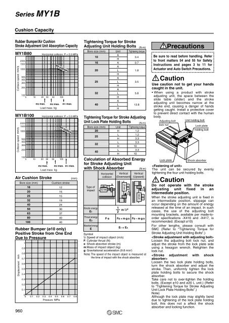
Series <strong>MY1B</strong>Cushion CapacityRubber Bumper/Air CushionStroke Adjustment Unit Absorption Capacity<strong>MY1B</strong>80Collision speed mm/s<strong>MY1B</strong>100Collision speed mm/sDisplacement mm2000150010005004003002001005 10 20 30 50 100200015001000500400300200Horizontal collision: P = 0.5 MPaAir cushionm2 max. m3 max. m1 max.Load mass kgHorizontal collision: P = 0.5 MPa1005 10 20 30 50 100Air Cushion StrokeAir cushionm2 max. m3 max. m1 max.Load mass kgRubber Bumper (ø10 only)Positive Stroke from One EndDue to Pressure960Bore size (mm)162025324050638010010.90.80.70.60.50.40.30.20.1(mm)Cushion stroke12151519243037404000 0.1 0.2 0.3 0.4 0.5 0.6 0.7 0.8Pressure MPaTightening Torque for StrokeAdjusting Unit Holding BoltsBore size (mm)101620253240UnitAHAALHALHALHALH(N·m)Tightening torque0.40.71.83.55.813.8Tightening Torque for Stroke AdjustingUnit Lock Plate Holding BoltsBore size (mm)20253240UnitHLHLHLH(N·m)Tightening torque1.21.23.33.3103.310Calculation of Absorbed Energyfor Stroke Adjusting Unitwith Shock Absorber(N·m)Type ofimpactKinetic energyE1Thrust energyE2Absorbed energyEHorizontalcollisionυ msVertical(Downward)12υ mm·υ 2sVertical(Upward)sυ mF·s Fs + m·g·s Fs – m·g·sE1 + E2Symbolυ: Speed of impact object (m/s)F: Cylinder thrust (N)s: Shock absorber stroke (m)m:Mass of impact object (kg)g: Gravitational acceleration (9.8 m/s 2 )Note) The speed of the impact object is measured atthe time of impact with the shock absorber.PrecautionsBe sure to read before handling. Referto front matters 54 and 55 for SafetyInstructions and pages 3 to 11 forActuator and Auto Switch Precautions.CautionUse caution not to get your handscaught in the unit.• When using a product with strokeadjusting unit, the space between theslide table (slider) and the strokeadjusting unit becomes narrow at thestroke end, causing a danger of handsgetting caught. Install a protective coverto prevent direct contact with the humanbody.Adjusting boltlock nutUnit holding boltLock plateShock absorberThe unit can be secured by evenlytightening the four unit holding bolts.CautionLock plateholding boltDo not operate with the strokeadjusting unit fixed in anintermediate position.When the stroke adjusting unit is fixed inan intermediate position, slippage canoccur depending on the amount of energyreleased at the time of an impact. In suchcases, the use of the adjusting boltmounting brackets, available per made-toorderspecifications -X416 and -X417, isrecommended. (Except ø10)For other lengths, please consult with<strong>SMC</strong> (Refer to “Tightening Torque forStroke Adjusting Unit Holding Bolts”.)Loosen the adjusting bolt lock nut, andadjust the stroke from the lock plate sideusing a hexagon wrench. Retighten thelock nut.Loosen the two lock plate holding bolts,turn the shock absorber and adjust thestroke. Then, uniformly tighten the lockplate holding bolts to secure the shockabsorber.Take care not to over-tighten the holdingbolts. (Except ø10 and ø20 L unit.) (Referto “Tightening Torque for Stroke AdjustingUnit Lock Plate Holding Bolts”.)Note)Although the lock plate may slightly benddue to tightening of the lock plate holdingbolt, this does not a affect the shockabsorber and locking function.


