

Fusion Programme - ENEA - Fusione
Fusion Programme - ENEA - Fusione
Fusion Programme - ENEA - Fusione
- No tags were found...

Create successful ePaper yourself
Turn your PDF publications into a flip-book with our unique Google optimized e-Paper software.
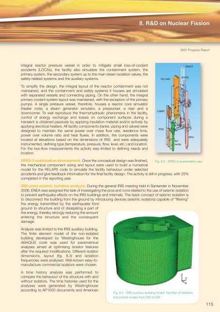
8. R&D on Nuclear Fission2007 Progress Reportintegral reactor pressure vessel in order to mitigate small loss-of-coolantaccidents (LOCAs), the facility also simulates the containment system, theprimary system, the secondary system up to the main steam isolation valves, thesafety-related systems and the auxiliary systems.Dry-wellEHRSRWSTTo simplify the design, the integral layout of the reactor containment was notmaintained, and the containment and safety systems it houses are simulatedwith separated vessels and connecting piping. On the other hand, the integralprimary coolant system layout was maintained, with the exception of the primarypumps. A single pressure vessel, therefore, houses a reactor core simulator(heater rods), a steam generator simulator, a pressuriser, a riser and adowncomer. To well reproduce the thermohydraulic phenomena in the facility,control of energy exchange and losses on component surfaces during atransient is obtained passively by applying insulation material and/or actively byapplying electrical heaters. All facility components (tanks, piping and valves) weredesigned to maintain the same power over mass flow rate, residence time,power over volume ratio and heat fluxes. In addition, the components werelocated at elevations based on the dimensions of IRIS and were adequatelyinstrumented, defining type (temperature, pressure, flow, level, etc.) and location.For the two-flow measurements the activity was limited to defining needs andlocation.LGMSPSSEBTADPRVcavityQTRPVSPES-3 nodalization development. Once the conceptual design was finished, Fig. 8.2 - SPES-3 axonometric viewthe mechanical component sizing and layout were used to build a numericalmodel for the RELAP5 code to simulate the facility behaviour under selectedaccidents and give feedback information for the final facility design. The activity is still in progress, with 25%completed in the reporting year.IRIS plant seismic isolation analysis. During the general IRIS meeting held in Santander in November2006, <strong>ENEA</strong> was assigned the task of investigating the pros and cons related to the use of seismic isolationto prevent earthquake effects on the IRIS buildings and internals. The basic concept of seismic isolation isto disconnect the building from the ground by introducing devices (seismic isolators) capable of “filtering”the energy transmitted by the earthquake fromground to structure and of dissipating a part ofthe energy, thereby strongly reducing the amountentering the structure and the consequentdamage.Analysis was limited to the IRIS auxiliary building.The finite element model of the non-isolatedbuilding developed by Westinghouse for theABAQUS code was used for parametricalanalyses aimed at optimising isolator featuresafter the required modifications. Different isolatordimensions, layout (fig. 8.3) and isolationfrequencies were analysed. Well-known easy-tomanufacturecommercial isolators were chosen.A time history analysis was performed tocompare the behaviour of the structure with andwithout isolators. The time histories used for theanalyses were generated by Westinghouseaccording to AP1000 documents and AmericanZYXFig. 8.3 - IRIS auxiliary building model. Number of isolators(red points) ranges from 200 to 250115


