

Fusion Programme - ENEA - Fusione
Fusion Programme - ENEA - Fusione
Fusion Programme - ENEA - Fusione
- No tags were found...

Create successful ePaper yourself
Turn your PDF publications into a flip-book with our unique Google optimized e-Paper software.
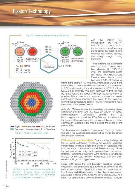
Fission Technology0.16 mm 0.16 mm0.6 mm 0.6 mm13.63 mm 13.54 mmFuel inner57% MgO7.1 mm VF(Pellet)=21.053%8.0 mm7.42 mm Filling ρ=0.91568.32 mm8.62 mm VF(Steel)=16.021%9.52 mmFuelVoidSSPb5.01mmFig. 8.16 - Three fuel assembly types (same hexcan)(750°C)(480°C)(440°C)Fuel interm50% MgO191 mm186 mm178 mm168+1 Fuel pins(7+1 pins rows)FuelFuel outer50% MgO(750°C)4.02mmFuel outer50% MgOVF(Pellet)=26.729%Filling ρ=0.92456VF(Steel)=16.923%and the related fuelcomposition (Pu 45.7%,MA 54.3% in vol.), whichimplies a rather small reactivityswing along the cycle, a newcore was laid down to increasethe safety margin duringtransients.Three different fuel assemblieswith the same hexcan havebeen designed (fig. 8.16). Theinner and intermediate zonesare fuelled with geometricallyidentical assemblies and pins,but with a different content ofmatrix in the pellets (57% inner, 50% intermediate), while in theouter zone the pin diameter has been increased (from 8.62 mmto 9.52 mm), keeping the matrix content at 50%. The threetypes of fuel assembly have been arranged so that the core(fig. 8.17) flattens the radial distribution power as much aspossible. This accounts for a narrow excursion of the coolantoutlet temperatures, increasing the margin to the maximumallowed clad temperature (823 K). Figure 8.18 shows the radialdistribution of the power density.2007 Progress ReportPD hom (W/cm 3 )12010080604020TargetFuel 3 outerFuel 1 inner Fuel 2 intermediateBox dummy Hot FA per zoneFig. 8.17 - Three-zone core arrangementMax zone 1 (1 year)Max zone 2,3 (1 year)Max zone 1 (2 years)Max zone 2,3 (2 years)}}BOCEOCPD Radial distributions at about AH/2 (400 MW)040 60 80 100 120 140 160R (cm)Fig. 8.18 - Radial power density distribution (R,zanalysis). Horizontal lines: correspondingmaximums which vary with zone as thermalconduction varies with matrix contentsA detailed 3D analysis gave the assembly-by-assembly powerdistribution (fig. 8.19) and the peak pin power for furtherthermohydraulic verification carried out byForschungszeuntrum Karlsruh (FZK) Germany. It is clear fromthe figure that by rearranging the contours of the zone anotheroptimisation is possible, but this is outside the scope of thepresent FP6.The three-zone core has been characterised. The large positivevoid effect (fig. 8.20) has been confirmed, as well as the almostzero Doppler coefficient.EFIT pin mechanical analysis. Spacers along the height ofthe pin avoid undesirable vibrations but produce significantconcentrated pressure drops and points of weakness thatopen the way to corrosion of the lead. Therefore a key point ofthe mechanical pin design is to optimise their number andstiffness. Parametric evaluations were performed for differentdegrees of stiffness, different interspaces and boundaryconstraint(hinge, joint) hypotheses.Figure 8.21 shows the joint boundary condition, vibrationfrequencies and amplitudes as a function of stiffness for thecase of five spacers. Table 8.IV shows, for each selectedhypotheses, and different space number, the frequencies andamplitudes in terms of the Chen-Weber model X max /d h . As aresult, five spacers have been chosen with stiffness no higher124


