Combustion Air and VentingVentilation and Combustion AirRequirements - Direct VentA Direct Vent appliance utilizes uncontaminedoutdoor air (piped directly to the appliance) forcombustion)For Direct Vent installations, involving onlythe PRESTIGE Solo, in which the minimumservice clearances are maintained as listed onpage 4, no ventilation openings are required.For Direct Vent, zero clearance installationsinvolving only the PRESTIGE Solo, the space/ enclosure must provide two openings for ventilation.The openings must be sized to provide1 square inch of free area per 1,000 BTUH ofboiler input. The openings shall be placed 12inches from the top of the space and 12 inchesfrom the floor of the space.For installations in which the PRESTIGE Soloshares the space with air movers (exhaust fan,clothes dryers, fireplaces, etc.) and other combustionequipment (gas or oil) the space mustbe provided with adequate air openings to provideventilation and combustion air to theequipment. To properly size the ventilation /combustion air openings, the installer mustcomply with the National Fuel Gas CodeNFPA 54, ANSI Z223.1 for installations in theU.S or CSA B149.1 and B149.2 for installationsin Canada.WARNINGThe space must be provided with ventilation/ combustion air openings properlysized for all make-up air requirements(exhaust fans, clothes dryers, fireplaces,etc.) and the total input of all applianceslocated in the same space as the PRES-TIGE Solo, excluding the input of aDirect Vent PRESTIGE Solo which usescombustion air directly from the outside,thus additional free area for the openingsis not required. Failure to provideor properly size the openings couldresult in severe personal injury, death orsubstantial property damage.Ventilation and Combustion AirRequirements - Category IVA Category IV appliance utilizes uncontaminatedindoor or outdoor air (surrounding theappliance) for combustion.BEST PRACTICEIn order to reduce the potential risksassociated with indoor contaminates(listed on page 5), flammable vapors andtight housing construction (little or noinfiltration air), it is recommended topipe uncontaminated combustion airdirectly from the outdoors to the appliance.This practice also promotes highersystem efficiency by reducing heatedindoor air from being exhausted fromthe house and replaced by cold infiltrationair into the house.For installations in which the PRESTIGE Soloshares the space with air movers (exhaust fan,clothes dryers, fireplaces, etc.) and other combustionequipment (gas or oil) the space must beprovided with adequate air openings to provideventilation and combustion air to the equipment.To properly size the ventilation / combustion airopenings, the installer must comply with theNational Fuel Gas Code NFPA 54, ANSI Z223.1for installations in the U.S or CSA B149.1 andB149.2 for installations in Canada, as referencedin this section of the manual and titled Methodsof Accessing Combustion Air into a Space.WARNINGThe space must be provided with ventilation/ combustion air openings properlysized for all make-up air requirements(exhaust fans, clothes dryers, fireplaces,etc.) and the total input of all appliancesincluding the PRESTIGE Solo whenlocated in the same space. Failure to provideor properly size the openings couldresult in severe personal injury, death orsubstantial property damage.6
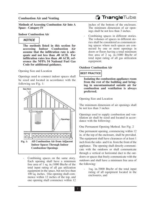
Combustion Air and VentingMethods of Accessing Combustion Air Into ASpace - Category IVIndoor Combustion AirNOTICEThe methods listed in this section foraccessing Indoor Combustion Airassume that the infiltration rate is adequateand not less than .40 ACH. Forinfiltration rates less than .40 ACH, referencethe NFPA 54 National Fuel GasCode for additional guidance.Opening Size and LocationOpenings used to connect indoor spaces shallbe sized and located in accordance with thefollowing see Fig. 1:inches of the bottom of the enclosure.The minimum dimension of air openingsshall be not less than 3 inches.- Combining spaces in different stories.The volumes of spaces in different storiesshall be considered as communicatingspaces where such spaces are connectedby one or more openings indoors or floors having a total minimumfree area of 2 sq. in./1000 Btu/hr oftotal input rating of all gas utilizationequipment.Outdoor Combustion AirBEST PRACTICEIsolating the combustion appliance roomfrom the rest of the building and bringingin uncontaminated outside air forcombustion and ventilation is alwayspreferred.Opening Size and LocationThe minimum dimension of air openings shallbe not less than 3 inchesOpenings used to supply combustion and ventilationair shall be sized and located in accordancewith the following:Fig. 1:All Combustion Air from AdjacentIndoor Spaces Through IndoorCombustion Openings- Combining spaces on the same story.Each opening shall have a minimumfree area of 1 sq. in./1000 Btu/hr of thetotal input rating of all gas utilizationequipment in the space, but not less than100 sq. inches. One opening shall commencewithin 12 inches of the top, andone opening shall commence within 12One Permanent Opening Method. See Fig. 2One permanent opening, commencing within 12in. of the top of the enclosure, shall be provided.The equipment shall have clearances of at least 1inch from the sides and 6 in. from the front of theappliance. The opening shall directly communicatewith the outdoors or shall communicatethrough a vertical or horizontal duct to the outdoorsor spaces that freely communicate with theoutdoors and shall have a minimum free area ofthe following:- 1sq. in./3000 Btu/hr of the total inputrating of all equipment located in theenclosures, and7