Simulation of Third Generation CDMA Systems - Virginia Tech
Simulation of Third Generation CDMA Systems - Virginia Tech
Simulation of Third Generation CDMA Systems - Virginia Tech

You also want an ePaper? Increase the reach of your titles
YUMPU automatically turns print PDFs into web optimized ePapers that Google loves.
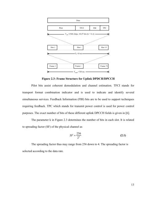
DataPilotTFCI FBI TPCT slot =2560 chips, 10×2 k bits (k = 0..6)Slot 1 Slot i Slot 15T f =10 msFrame 1 Frame i Frame 72T super =720 msFigure 2.3: Frame Structure for Uplink DPDCH/DPCCHPilot bits assist coherent demodulation and channel estimation. TFCI stands fortransport format combination indicator and is used to indicate and identify severalsimultaneous services. Feedback Information (FBI) bits are to be used to support techniquesrequiring feedback. TPC which stands for transmit power control is used for power controlpurposes. The exact number <strong>of</strong> bits <strong>of</strong> these different uplink DPCCH fields is given in [6].The parameter k in Figure 2.3 determines the number <strong>of</strong> bits in each slot. It is relatedto spreading factor (SF) <strong>of</strong> the physical channel asSF= 256k2(2.1)The spreading factor thus may range from 256 down to 4. The spreading factor isselected according to the data rate.13