Simulation of Third Generation CDMA Systems - Virginia Tech
Simulation of Third Generation CDMA Systems - Virginia Tech
Simulation of Third Generation CDMA Systems - Virginia Tech

You also want an ePaper? Increase the reach of your titles
YUMPU automatically turns print PDFs into web optimized ePapers that Google loves.
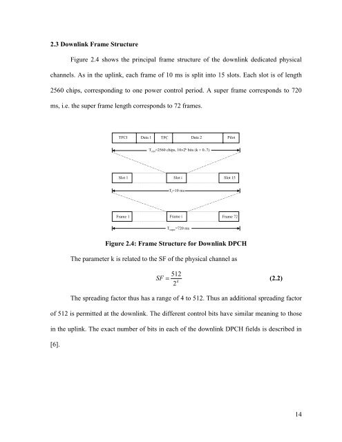
2.3 Downlink Frame StructureFigure 2.4 shows the principal frame structure <strong>of</strong> the downlink dedicated physicalchannels. As in the uplink, each frame <strong>of</strong> 10 ms is split into 15 slots. Each slot is <strong>of</strong> length2560 chips, corresponding to one power control period. A super frame corresponds to 720ms, i.e. the super frame length corresponds to 72 frames.TFCI Data 1 TPC Data 2 PilotT slot =2560 chips, 10×2 k bits (k = 0..7)Slot 1 Slot i Slot 15T f =10 msFrame 1 Frame i Frame 72T super =720 msFigure 2.4: Frame Structure for Downlink DPCHThe parameter k is related to the SF <strong>of</strong> the physical channel asSF= 512k2(2.2)The spreading factor thus has a range <strong>of</strong> 4 to 512. Thus an additional spreading factor<strong>of</strong> 512 is permitted at the downlink. The different control bits have similar meaning to thosein the uplink. The exact number <strong>of</strong> bits in each <strong>of</strong> the downlink DPCH fields is described in[6].14