Simulation of Third Generation CDMA Systems - Virginia Tech
Simulation of Third Generation CDMA Systems - Virginia Tech
Simulation of Third Generation CDMA Systems - Virginia Tech

Create successful ePaper yourself
Turn your PDF publications into a flip-book with our unique Google optimized e-Paper software.
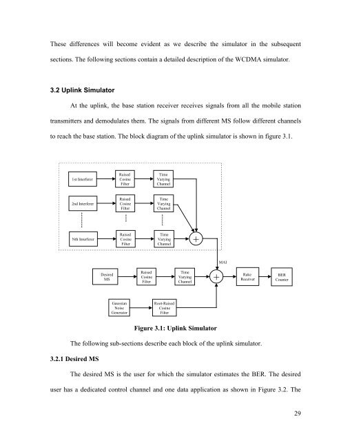
These differences will become evident as we describe the simulator in the subsequentsections. The following sections contain a detailed description <strong>of</strong> the W<strong>CDMA</strong> simulator.3.2 Uplink SimulatorAt the uplink, the base station receiver receives signals from all the mobile stationtransmitters and demodulates them. The signals from different MS follow different channelsto reach the base station. The block diagram <strong>of</strong> the uplink simulator is shown in figure 3.1.1st InterfererRaisedCosineFilterTimeVaryingChannel2nd InterfererRaisedCosineFilterTimeVaryingChannelNth InterfererRaisedCosineFilterTimeVaryingChannel+MAIDesiredMSRaisedCosineFilterTimeVaryingChannel+RakeReceiverBERCounterGaussianNoiseGeneratorRoot-RaisedCosineFilterFigure 3.1: Uplink SimulatorThe following sub-sections describe each block <strong>of</strong> the uplink simulator.3.2.1 Desired MSThe desired MS is the user for which the simulator estimates the BER. The desireduser has a dedicated control channel and one data application as shown in Figure 3.2. The29