Simulation of Third Generation CDMA Systems - Virginia Tech
Simulation of Third Generation CDMA Systems - Virginia Tech
Simulation of Third Generation CDMA Systems - Virginia Tech

Create successful ePaper yourself
Turn your PDF publications into a flip-book with our unique Google optimized e-Paper software.
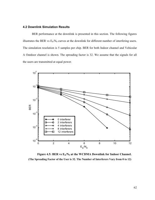
4.2 Downlink <strong>Simulation</strong> ResultsBER performance at the downlink is presented in this section. The following figuresillustrates the BER vs E b /N 0 curves at the downlink for different number <strong>of</strong> interfering users.The simulation resolution is 5 samples per chip. BER for both Indoor channel and VehicularA Outdoor channel is shown. The spreading factor is 32. We assume that the signals for allthe users are transmitted at equal power.10 0 E b/N 010 -110 -2BER10 -310 -40 interferer2 interferers4 interferers8 interferers12 interferers10 -50 2 4 6 8 10 12Figure 4.5: BER vs E b /N 0 at the W<strong>CDMA</strong> Downlink for Indoor Channel.(The Spreading Factor <strong>of</strong> the User is 32. The Number <strong>of</strong> Interferers Vary from 0 to 12)62