Simulation of Third Generation CDMA Systems - Virginia Tech
Simulation of Third Generation CDMA Systems - Virginia Tech
Simulation of Third Generation CDMA Systems - Virginia Tech

You also want an ePaper? Increase the reach of your titles
YUMPU automatically turns print PDFs into web optimized ePapers that Google loves.
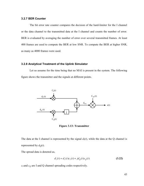
3.2.7 BER CounterThe bit error rate counter compares the decision <strong>of</strong> the hard-limiter for the I channelor the data channel to the transmitted data at the I channel and counts the number <strong>of</strong> error.BER is evaluated by averaging the number <strong>of</strong> error over several transmitted frames. At least400 frames are used to compute the BER at low SNR. To compute the BER at higher SNR,as many as 4000 frames were used.3.2.8 Analytical Treatment <strong>of</strong> the Uplink SimulatorLet us assume for the time being that no MAI is present in the system. The followingfigure shows the transmitter and the signals at different points.C I (t)d I (t)C SC (t)d s(t)s(t)d Q (t)jC Q (t)Figure 3.13: TransmitterThe data at the I channel is represented by the signal d I (t), while the data at the Q channel isrepresented by d Q (t).The spread data is denoted as,d () t = d () t c () t + jd () t c () t(3.22)s I I Q Qc I and c Q are I and Q channel spreading codes respectively.43