Simulation of Third Generation CDMA Systems - Virginia Tech
Simulation of Third Generation CDMA Systems - Virginia Tech
Simulation of Third Generation CDMA Systems - Virginia Tech

You also want an ePaper? Increase the reach of your titles
YUMPU automatically turns print PDFs into web optimized ePapers that Google loves.
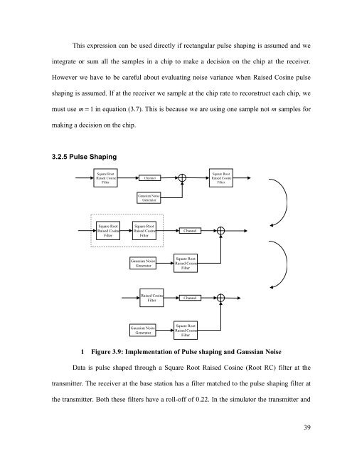
This expression can be used directly if rectangular pulse shaping is assumed and weintegrate or sum all the samples in a chip to make a decision on the chip at the receiver.However we have to be careful about evaluating noise variance when Raised Cosine pulseshaping is assumed. If at the receiver we sample at the chip rate to reconstruct each chip, wemust use m = 1 in equation (3.7). This is because we are using one sample not m samples formaking a decision on the chip.3.2.5 Pulse ShapingSquare RootRaised CosineFilterChannelSquare RootRaised CosineFilterGaussian NoiseGeneratorSquare RootRaised CosineFilterSquare RootRaised CosineFilterChannelGaussian NoiseGeneratorSquare RootRaised CosineFilterRaised CosineFilterChannelGaussian NoiseGeneratorSquare RootRaised CosineFilter1 Figure 3.9: Implementation <strong>of</strong> Pulse shaping and Gaussian NoiseData is pulse shaped through a Square Root Raised Cosine (Root RC) filter at thetransmitter. The receiver at the base station has a filter matched to the pulse shaping filter atthe transmitter. Both these filters have a roll-<strong>of</strong>f <strong>of</strong> 0.22. In the simulator the transmitter and39