Simulation of Third Generation CDMA Systems - Virginia Tech
Simulation of Third Generation CDMA Systems - Virginia Tech
Simulation of Third Generation CDMA Systems - Virginia Tech

You also want an ePaper? Increase the reach of your titles
YUMPU automatically turns print PDFs into web optimized ePapers that Google loves.
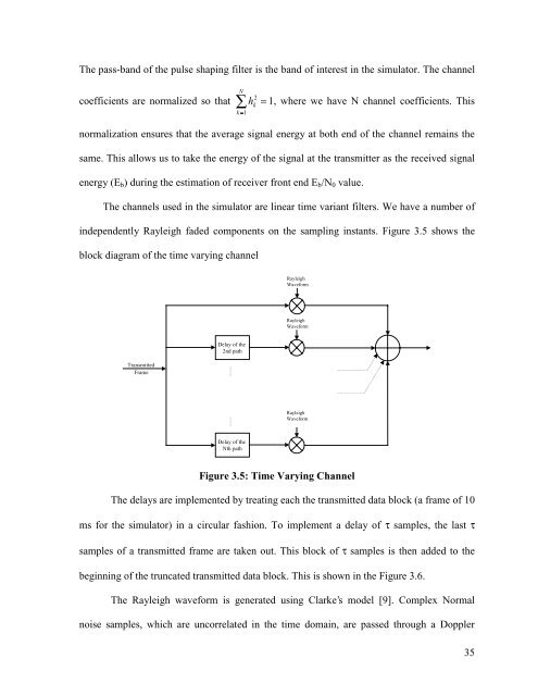
The pass-band <strong>of</strong> the pulse shaping filter is the band <strong>of</strong> interest in the simulator. The channelcoefficients are normalized so thatN2Ê h kk = 1= 1, where we have N channel coefficients. Thisnormalization ensures that the average signal energy at both end <strong>of</strong> the channel remains thesame. This allows us to take the energy <strong>of</strong> the signal at the transmitter as the received signalenergy (E b ) during the estimation <strong>of</strong> receiver front end E b /N 0 value.The channels used in the simulator are linear time variant filters. We have a number <strong>of</strong>independently Rayleigh faded components on the sampling instants. Figure 3.5 shows theblock diagram <strong>of</strong> the time varying channelRayleighWaveformRayleighWaveformTransmittedFrameDelay <strong>of</strong> the2nd pathRayleighWaveformDelay <strong>of</strong> theNth pathFigure 3.5: Time Varying ChannelThe delays are implemented by treating each the transmitted data block (a frame <strong>of</strong> 10ms for the simulator) in a circular fashion. To implement a delay <strong>of</strong> τ samples, the last τsamples <strong>of</strong> a transmitted frame are taken out. This block <strong>of</strong> τ samples is then added to thebeginning <strong>of</strong> the truncated transmitted data block. This is shown in the Figure 3.6.The Rayleigh waveform is generated using Clarke’s model [9]. Complex Normalnoise samples, which are uncorrelated in the time domain, are passed through a Doppler35