Technical Appendix Specifications for the RADIO SYSTEM UPGRADE
Technical Appendix Specifications for the RADIO SYSTEM UPGRADE
Technical Appendix Specifications for the RADIO SYSTEM UPGRADE
Create successful ePaper yourself
Turn your PDF publications into a flip-book with our unique Google optimized e-Paper software.
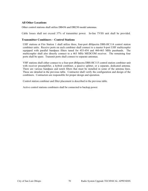
All O<strong>the</strong>r LocationsO<strong>the</strong>r control stations shall utilize DB436 and DB230 model antennas.Cable losses shall not exceed 37% of transmitter power. In-line TVSS unit shall be provided.Transmitter Combiners – Control StationsUHF stations at Fire Station 1 shall utilize three, four-port dbSpectra DBS-HC114 control stationcombiner units. Receive ports on each combiner shall connect to a master 8-port UHF multicouplerequipped with parallel bandpass filters tuned <strong>for</strong> 453-454 and 460-463 MHz passbands. Themulticoupler shall also directly connect to a 463 MHz MEDCOM receiver. The remaining fourports shall be spare. Transmit ports shall connect to separate antennas.VHF stations shall ei<strong>the</strong>r connect to a four-port dbSpectra DBS-HC115 control station combiner unitwith receiver preamplifier, a hybrid combiner, a passive splitter, or a separate, dedicated antenna.There are various bandpass and notch filters that must be installed in some of <strong>the</strong> antenna lines.These are detailed in <strong>the</strong> previous table. Contractor shall verify <strong>the</strong> configuration and design of <strong>the</strong>combiners. Contractors are responsible <strong>for</strong> proper design and operation.Control station combiner and filter placement is described in <strong>the</strong> previous table.Active control stations combiners shall be connected to backup power.City of San Luis Obispo 70 Radio System Upgrade TECHNICAL APPENDIX


