Liebert Challenger 3000
Liebert Challenger™ 3000 Operation & Maintenance Manual - DCES
Liebert Challenger™ 3000 Operation & Maintenance Manual - DCES

Create successful ePaper yourself
Turn your PDF publications into a flip-book with our unique Google optimized e-Paper software.
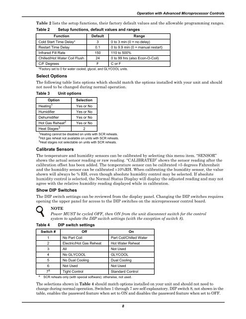
Operation with Advanced Microprocessor ControlsTable 2 lists the setup functions, their factory default values and the allowable programming ranges.Table 2Setup functions, default values and rangesFunction Default RangeCold Start Time Delay* 3 0 to 3 min (0 = no delay)Restart Time Delay 0.1 0 to 9.9 min (0 = manual restart)Infrared Fill Rate 150 110 to 500%Chilled/Hot Water Coil Flush 24 0 to 99 hrs (also Econ-O-Coil)C/F Degrees F C or F*Factory set to 0 for water cooled, glycol, and GLYCOOL units.Select OptionsThe following table lists options which should match the options installed with your unit and shouldnot need to be changed during normal operation.Table 3Unit optionsOption SelectionHeating 1Yes or NoHumidifierYes or NoDehumidifier Yes or NoHot Gas Reheat 2 Yes or NoHeat Stages 3 21 Heating cannot be disabled on units with SCR reheats.2 Hot gas reheat not available on units with SCR reheats.3 Heat stages not selectable on units with SCR reheats.Calibrate SensorsThe temperature and humidity sensors can be calibrated by selecting this menu item. “SENSOR”shows the actual sensor reading or raw reading. “CALIBRATED” shows the sensor reading after thecalibration offset has been added. The temperature sensor can be calibrated ±5 degrees Fahrenheitand the humidity sensor can be calibrated ±10%RH. When calibrating the humidity sensor, the valueshown will always be % RH, even though absolute humidity control may be selected. If absolutehumidity control is selected, the Normal Status Display will display the adjusted reading and may notagree with the relative humidity reading displayed while in calibration.Show DIP SwitchesThe DIP switch settings can be reviewed from the display panel. Changing the DIP switches requiresopening the upper panel for access to the DIP switches on the microprocessor control board.NOTEPower MUST be cycled OFF, then ON from the unit disconnect switch for the controlsystem to update the DIP switch settings (with the exception of switch 8).Table 4DIP switch settingsSwitch # Off On1 No Part Coil Part Coil/Chilled Water2 Electric/Hot Gas Reheat Hot Water Reheat3 All Not Used4 No GLYCOOL GLYCOOL5 No Dual Cooling Dual Cooling6 Not Used Not Useda7 a Tight Control Standard ControlSCR reheats only (with special software); otherwise, not used.The selections shown in Table 4 should match options installed on your unit and should not need tochange during normal operation. Switches 1 through 7 are self explanatory. DIP switch 8, not shown in thetable, enables the password feature when set to ON and disables the password feature when set to OFF.8