Liebert Challenger 3000
Liebert Challenger™ 3000 Operation & Maintenance Manual - DCES
Liebert Challenger™ 3000 Operation & Maintenance Manual - DCES
Create successful ePaper yourself
Turn your PDF publications into a flip-book with our unique Google optimized e-Paper software.
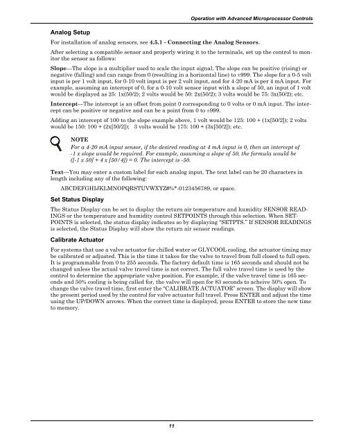
Analog SetupOperation with Advanced Microprocessor ControlsFor installation of analog sensors, see 4.5.1 - Connecting the Analog Sensors.After selecting a compatible sensor and properly wiring it to the terminals, set up the control to monitorthe sensor as follows:Slope—The slope is a multiplier used to scale the input signal. The slope can be positive (rising) ornegative (falling) and can range from 0 (resulting in a horizontal line) to ±999. The slope for a 0-5 voltinput is per 1 volt input, for 0-10 volt input is per 2 volt input, and for 4-20 mA is per 4 mA input. Forexample, assuming an intercept of 0, for a 0-10 volt sensor input with a slope of 50, an input of 1 voltwould be displayed as 25: 1x(50/2); 2 volts would be 50: 2x(50/2); 3 volts would be 75: 3x(50/2); etc.Intercept—The intercept is an offset from point 0 corresponding to 0 volts or 0 mA input. The interceptcan be positive or negative and can be a point from 0 to ±999.Adding an intercept of 100 to the slope example above, 1 volt would be 125: 100 + (1x[50/2]); 2 voltswould be 150: 100 + (2x[50/2]); 3 volts would be 175: 100 + (3x[50/2]); etc.NOTEFor a 4-20 mA input sensor, if the desired reading at 4 mA input is 0, then an intercept of-1 x slope would be required. For example, assuming a slope of 50, the formula would be([-1 x 50] + 4 x [50/4]) = 0. The intercept is -50.Text—You may enter a custom label for each analog input. The text label can be 20 characters inlength including any of the following:ABCDEFGHIJKLMNOPQRSTUVWXYZ#%*-0123456789, or space.Set Status DisplayThe Status Display can be set to display the return air temperature and humidity SENSOR READ-INGS or the temperature and humidity control SETPOINTS through this selection. When SET-POINTS is selected, the status display indicates so by displaying “SETPTS.” If SENSOR READINGSis selected, the Status Display will show the return air sensor readings.Calibrate ActuatorFor systems that use a valve actuator for chilled water or GLYCOOL cooling, the actuator timing maybe calibrated or adjusted. This is the time it takes for the valve to travel from full closed to full open.It is programmable from 0 to 255 seconds. The factory default time is 165 seconds and should not bechanged unless the actual valve travel time is not correct. The full valve travel time is used by thecontrol to determine the appropriate valve position. For example, if the valve travel time is 165 secondsand 50% cooling is being called for, the valve will open for 83 seconds to acheive 50% open. Tochange the valve travel time, first enter the “CALIBRATE ACTUATOR” screen. The display will showthe present period used by the control for valve actuator full travel. Press ENTER and adjust the timeusing the UP/DOWN arrows. When the correct time is displayed, press ENTER to store the new timeto memory.11


