Liebert Challenger 3000
Liebert Challenger™ 3000 Operation & Maintenance Manual - DCES
Liebert Challenger™ 3000 Operation & Maintenance Manual - DCES

You also want an ePaper? Increase the reach of your titles
YUMPU automatically turns print PDFs into web optimized ePapers that Google loves.
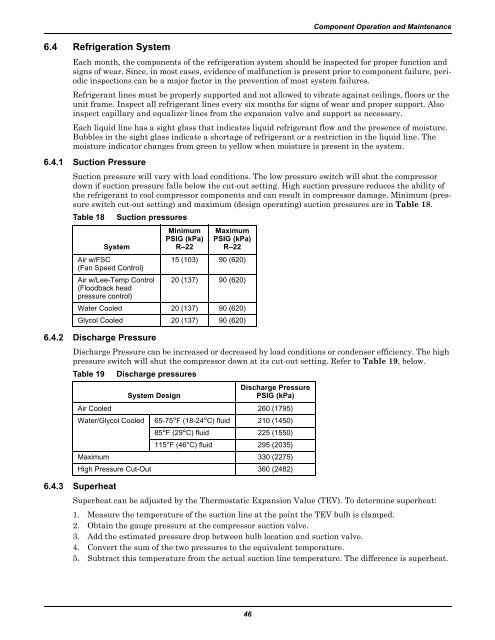
6.4 Refrigeration SystemComponent Operation and MaintenanceEach month, the components of the refrigeration system should be inspected for proper function andsigns of wear. Since, in most cases, evidence of malfunction is present prior to component failure, periodicinspections can be a major factor in the prevention of most system failures.Refrigerant lines must be properly supported and not allowed to vibrate against ceilings, floors or theunit frame. Inspect all refrigerant lines every six months for signs of wear and proper support. Alsoinspect capillary and equalizer lines from the expansion valve and support as necessary.Each liquid line has a sight glass that indicates liquid refrigerant flow and the presence of moisture.Bubbles in the sight glass indicate a shortage of refrigerant or a restriction in the liquid line. Themoisture indicator changes from green to yellow when moisture is present in the system.6.4.1 Suction PressureSuction pressure will vary with load conditions. The low pressure switch will shut the compressordown if suction pressure falls below the cut-out setting. High suction pressure reduces the ability ofthe refrigerant to cool compressor components and can result in compressor damage. Minimum (pressureswitch cut-out setting) and maximum (design operating) suction pressures are in Table 18.Table 18 Suction pressures6.4.2 Discharge PressureDischarge Pressure can be increased or decreased by load conditions or condenser efficiency. The highpressure switch will shut the compressor down at its cut-out setting. Refer to Table 19, below.Table 19 Discharge pressuresDischarge PressureSystem DesignPSIG (kPa)Air Cooled 260 (1795)Water/Glycol Cooled 65-75°F (18-24°C) fluid 210 (1450)85°F (29°C) fluid 225 (1550)115°F (46°C) fluid 295 (2035)Maximum 330 (2275)High Pressure Cut-Out 360 (2482)6.4.3 SuperheatSystemMinimumPSIG (kPa)R–22MaximumPSIG (kPa)R–22Air w/FSC15 (103) 90 (620)(Fan Speed Control)Air w/Lee-Temp Control 20 (137) 90 (620)(Floodback headpressure control)Water Cooled 20 (137) 90 (620)Glycol Cooled 20 (137) 90 (620)Superheat can be adjusted by the Thermostatic Expansion Value (TEV). To determine superheat:1. Measure the temperature of the suction line at the point the TEV bulb is clamped.2. Obtain the gauge pressure at the compressor suction valve.3. Add the estimated pressure drop between bulb location and suction valve.4. Convert the sum of the two pressures to the equivalent temperature.5. Subtract this temperature from the actual suction line temperature. The difference is superheat.46