Liebert Challenger 3000
Liebert Challenger™ 3000 Operation & Maintenance Manual - DCES
Liebert Challenger™ 3000 Operation & Maintenance Manual - DCES

Create successful ePaper yourself
Turn your PDF publications into a flip-book with our unique Google optimized e-Paper software.
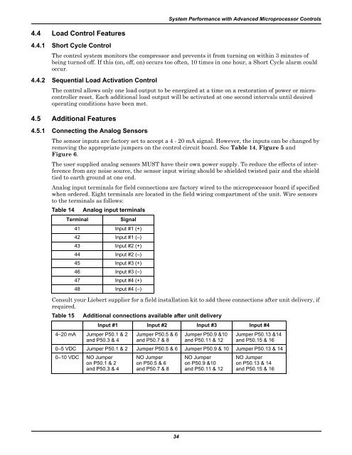
System Performance with Advanced Microprocessor Controls4.4 Load Control Features4.4.1 Short Cycle ControlThe control system monitors the compressor and prevents it from turning on within 3 minutes ofbeing turned off. If this (on, off, on) occurs too often, 10 times in one hour, a Short Cycle alarm couldoccur.4.4.2 Sequential Load Activation ControlThe control allows only one load output to be energized at a time on a restoration of power or microcontrollerreset. Each additional load output will be activated at one second intervals until desiredoperating conditions have been met.4.5 Additional Features4.5.1 Connecting the Analog SensorsThe sensor inputs are factory set to accept a 4 - 20 mA signal. However, the inputs can be changed byremoving the appropriate jumpers on the control circuit board. See Table 14, Figure 5 andFigure 6.The user supplied analog sensors MUST have their own power supply. To reduce the effects of interferencefrom any noise source, the sensor input wiring should be shielded twisted pair and the shieldtied to earth ground at one end.Analog input terminals for field connections are factory wired to the microprocessor board if specifiedwhen ordered. Eight terminals are located in the field wiring compartment of the unit. Wire sensorsto the terminals as follows:Table 14Consult your <strong>Liebert</strong> supplier for a field installation kit to add these connections after unit delivery, ifrequired.Table 15TerminalAnalog input terminalsSignal41 Input #1 (+)42 Input #1 (–)43 Input #2 (+)44 Input #2 (–)45 Input #3 (+)46 Input #3 (–)47 Input #4 (+)48 Input #4 (–)Additional connections available after unit delivery4–20 mA Jumper P50.1 & 2and P50.3 & 4Input #1 Input #2 Input #3 Input #4Jumper P50.5 & 6and P50.7 & 8Jumper P50.9 &10and P50.11 & 12Jumper P50.13 &14and P50.15 & 160–5 VDC Jumper P50.1 & 2 Jumper P50.5 & 6 Jumper P50.9 & 10 Jumper P50.13 & 140–10 VDC NO Jumperon P50.1 & 2and P50.3 & 4NO Jumperon P50.5 & 6and P50.7 & 8NO Jumperon P50.9 &10and P50.11 & 12NO Jumperon P50.13 & 14and P50.15 & 1634