

rf - Free and Open Source Software
rf - Free and Open Source Software
rf - Free and Open Source Software
- No tags were found...

You also want an ePaper? Increase the reach of your titles
YUMPU automatically turns print PDFs into web optimized ePapers that Google loves.
,<br />
("("s "<br />
Unit<br />
Attenuator<br />
Edward A. Lawrence, WASSWD/6<br />
218 Haloid<br />
Ridgecrest, Calif. 93555<br />
Since the topic of "S meters" is a popular<br />
one among radio amateurs, a lot of time is<br />
spent describing these devices, usually along<br />
the lines of how generous or "Scotch" the<br />
meters are at the QTII of the parties in the<br />
QSO. After a few such QSO's, I decided to<br />
build an attenuatar, calibrated in "S" units.<br />
My aim was to attain an accuracy of I db or<br />
better, using 5% ~w resistors <strong>and</strong> simple<br />
construction so it would be easy to duplicate.<br />
What I wound up with is very similar to<br />
the attenuatar described on page 40, January<br />
'67, 73.<br />
As a sidelight, I started out by calculating<br />
both "tee" <strong>and</strong> " pi" pads, <strong>and</strong> used "pi"<br />
because all values of resistance are close to<br />
st<strong>and</strong>ard values, but (especially for high<br />
attenuation pads) the values for "tee" pacts<br />
can get quite small; <strong>and</strong> expensive.<br />
I figured the values required from the<br />
tables in the Allied's "Electronics Data<br />
H<strong>and</strong>book", page 8, 5th edition. (Allied<br />
Radio, 75c, full of good info.)<br />
Since HS" units are supposed to be 6 db, I<br />
figured data for steps of 1,2 ,4 <strong>and</strong> 8 times<br />
that amount, or 6,12,24 <strong>and</strong> 48 db. With<br />
these steps, any number from 0 to 15 "5"<br />
units of attenuation could be selected. However,<br />
8 "S" units proved to be too much for<br />
one step, as shown by the lowered attenuation<br />
at 30 MHz, due to the inherent shunt<br />
capacitance of the resistor used in the series<br />
leg, plus the stray capacitance of the switch.<br />
So I removed the 8 "S" unit step <strong>and</strong><br />
installed another 4 "5" unit step. This allows<br />
selected steps of attenuation from 0 to II<br />
"5" units.<br />
Here are the values I calculated, <strong>and</strong> the<br />
actual values used, based on 51 ohms. The<br />
steps are switched in series, as required for<br />
the desired attenuation.<br />
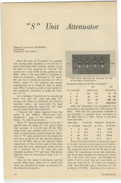
Front panel showing the switches for the<br />
various steps of attenuation.<br />
Resistance Values for 51 Ohm Attenuator:<br />
"S" units DB<br />
1 6 154 150 38 39<br />
2 12 85 82 96 100<br />
4 24 58 56 4ffi 390<br />
8 48 51.5 51 64006800<br />
After the attenuator was completed, the<br />
attenuation was measured at 3 kHz <strong>and</strong> at 30<br />
MHz. With the test equipment available it<br />
was possible to measure more accurately at<br />
30 MHz than at 3 kHz. Below is the data<br />
from the tests.<br />
Atten Step Predicted Measured Measured<br />
"S" units DB etten DB at 3 kH z at 30 MHz<br />
1 6 6.2 6.0 6.02<br />
2 12 12.3 12.2 12.16<br />
4 24 23.3 24.2 24.05<br />
8 48 48.5 47.5 39.11<br />
Now if we want to make an educated guess<br />
as to how far up we can expect good results.<br />
say I db error out of 24 db, then we can use<br />
the measured error in the 48 db step to calculate<br />
the capacitance across the series leg,<br />
<strong>and</strong> from that calculate the frequency where<br />
the I db error will occur. Go through the<br />
math if that is how you get your kicks, or<br />
take my word for it. It comes out to about<br />
2 pF. And this will cause a reduction of I db<br />
at about 220 MHz. And since the resistor is<br />
Rl<br />
ideal actual<br />
R2<br />
ideal actual<br />
14 73 MAGAZINE


