

rf - Free and Open Source Software
rf - Free and Open Source Software
rf - Free and Open Source Software
- No tags were found...

Create successful ePaper yourself
Turn your PDF publications into a flip-book with our unique Google optimized e-Paper software.
the b<strong>and</strong>. If you use both phone <strong>and</strong> CW, it<br />
might be well to make the design frequency<br />
near center of the b<strong>and</strong>. Likewise, the design<br />
freq uency may be made in the CW segment<br />
if you desire. Getting back to the swr<br />
measurements, you will note that at the antenna,<br />
or the base of the matching section, if<br />
one is used, the reflected power is nil across<br />
the greater portion of the design frequency,<br />
making the true swr unit. Next remove the<br />
swr meter from the driven element <strong>and</strong> reconnect<br />
the transmission line. There is no need to<br />
cut the transmission line to any particular<br />
length-just use r<strong>and</strong>om length to suit your<br />
purpose. Insert the swr meter at the transmitter<br />
end next <strong>and</strong> again make the full swr meter<br />
measurements across the b<strong>and</strong> every 50<br />
kHz as previously done with the swr meter at<br />
the antenna. Again, plot the curve on graph<br />
paper <strong>and</strong> note the similarity of the curves.<br />
Due to a multitude of factors, the transmitter<br />
end of the transmission line swr readings will<br />
tend to be somewhat lower at the b<strong>and</strong> end<br />
extremes.<br />
A dummy load may be substituted for the<br />
antenna. Heath's "Cantenna" is a good <strong>and</strong><br />
inexpensive one. The Waters dummy load<br />
power meter is excellent, but more expensive.<br />
An <strong>rf</strong> (thermo-couple) ammeter in the transmission<br />
line at the transmitter is worth its<br />
weight in gold <strong>and</strong> much more preferable to<br />
an in-line swr meter at the same point. Good<br />
Western Electric <strong>and</strong> G.E. <strong>rf</strong> ammeters may<br />
be purchased on the sur plus market for less<br />
than five dollars. After tuning <strong>and</strong> loading<br />
the transmitter to either the dummy load or<br />
the antenna there will be no change in transmission<br />
line current when switched from one<br />
to the other <strong>and</strong> no retuning of the transmitter<br />
should be necessary. This indicates as<br />
nearly as possible with available equipment<br />
whether your antenna is nonreactive or near<br />
pure resistive. If a Bird Model 43 in-line<br />
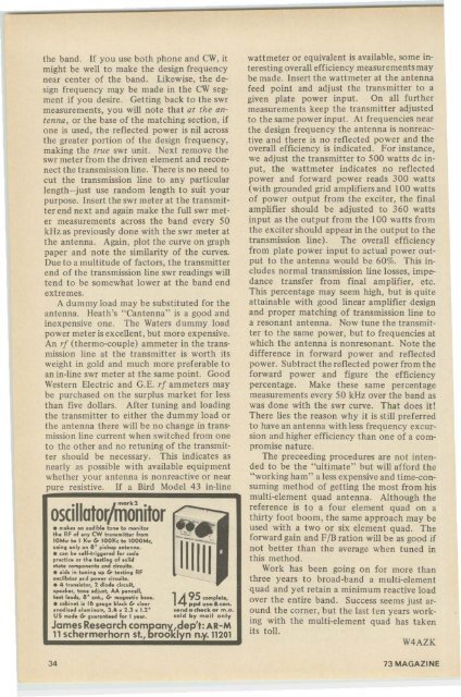
oscillator/monitor ~_.-<br />
8.-<br />
• mak•• an audibl. ton. to ....onitor<br />
the RF of any CW transmitt., from ,..;:'::":' ."<br />
IOM.... to I K.... lr IOOK~ to IOOOMc. 1- -'<br />
uling only an 8~ pi~kup ant.nn.. 11111-<br />
• un be ••If.trigg..... for ,od.<br />
~;;::i::.:;:::n~·~~dg~7:,:7~~<br />
• .id. in tuning up lr t.lting RF<br />
o.dll.to••r:d pow.r ,ir'uih.<br />
• # tr.n.iltor, 2 diod. ~i.~uit.<br />
'P""." ton••diu.t. A.A p.n,.II,<br />
t••t I••d., 8' .nt., lr m.,neti, ba...<br />
• ,.bin.t i. Ib taug. M.," lr ~I••r<br />
•"Wi••d .luminum, 3.4 • 2.3 • 1.2~<br />
US m.d.lr gun.nt.ed For I y....<br />
1495 ,ompl.,<br />
ppd ,...a&can.<br />
••nd a ch.~k or m.e,<br />
lold by mall only<br />
James Research campany',dep'l: AR-M<br />
11 schermerhorn Sl., brodkl n n.y.11201<br />
wattmeter or equivalent is available. some interesting<br />
overall efficiency measurements may<br />
be made. Insert the wattmeter at the antenna<br />
feed point <strong>and</strong> adjust the transmitter to a<br />
given plate power input. On all further<br />
measurements keep the transmitter adjusted<br />
to the same power input. At frequencies near<br />
the design frequency the antenna is nonreactive<br />
<strong>and</strong> there is no reflected power <strong>and</strong> the<br />
overall efficiency is indicated. For instance,<br />
we adjust the transmitter to 500 watts de input,<br />
the wattmeter indicates no reflected<br />
power <strong>and</strong> forward power reads 300 watts<br />
(with grounded grid amplifiers <strong>and</strong> 100 watts<br />
of power output from the exciter, the final<br />
amplifier should be adjusted to 360 watts<br />
input as the output from the 100 watts from<br />
the exciter should appear in the output to the<br />
transmission line). The overall efficiency<br />
from plate power input to actual power output<br />
to the antenna would be 60%. This includes<br />
normal transmission line losses, impedance<br />
transfer from final amplifier, etc.<br />
This percentage may seem high, but is quite<br />
attainable with good linear amplifier design<br />
<strong>and</strong> proper matching of transmission line to<br />
a resonant antenna. Now tune the transmit·<br />
ter to the same power, but to freq uencies at<br />
which the antenna is nonresonant. Note the<br />
difference in forward power <strong>and</strong> reflected<br />
power. Subtract the reflected power from the<br />
forward power <strong>and</strong> figure the efficiency<br />
percentage. Make these same percentage<br />
measurements every 50 kHz over the b<strong>and</strong> as<br />
was done with the swr curve. That does it!<br />
There lies the reason why it is still preferred<br />
to have an antenna with less frequency excursion<br />
<strong>and</strong> higher efficiency than one of a compromise<br />
nature.<br />
The preceeding procedures are not intended<br />
to be the "ultimate" but will afford the<br />
"working ham" a less expensive <strong>and</strong> time-consuming<br />
method of getting the most from his<br />
multi-element quad antenna. Although the<br />
reference is to a four element quad on a<br />
thirty foot boom, the same approach may be<br />
used with a two or six element quad. The<br />
forward gain <strong>and</strong> FIB ration will be as good if<br />
not better than the average when tuned in<br />
this method.<br />
Work has been going on for more than<br />
three years to broad-b<strong>and</strong> a multi-element<br />
quad <strong>and</strong> yet retain a minimum reactive load<br />
over the entire b<strong>and</strong>, Success seems just around<br />
the corner, but the last ten years working<br />
with the multi-element quad has taken<br />
its toll.<br />
W4AZK<br />
34 73 MAGAZINE


