Association
Magnetic Oxide Heterostructures: EuO on Cubic Oxides ... - JuSER
Magnetic Oxide Heterostructures: EuO on Cubic Oxides ... - JuSER
- No tags were found...

Create successful ePaper yourself
Turn your PDF publications into a flip-book with our unique Google optimized e-Paper software.
5.2. Thermodynamic analysis of the EuO/Si interface 97<br />
<br />
<br />
<br />
<br />
<br />
<br />
<br />
<br />
<br />
<br />
<br />
<br />
<br />
<br />
<br />
<br />
<br />
<br />
<br />
<br />
<br />
<br />
<br />
<br />
<br />
<br />
<br />
<br />
<br />
<br />
<br />
<br />
<br />
<br />
<br />
<br />
<br />
<br />
<br />
<br />
<br />
<br />
<br />
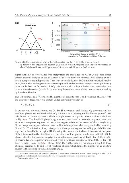
Figure 5.8.: Three growth regimes of EuO, illustrated in a Eu–O–Si Gibbs triangle (inset).<br />
(I) describes the oxygen-rich regime, (III) the Eu-rich EuO regime, and (II) can be referred to,<br />
when EuO is stabilized on (H-passivated) Si, as the stoichiometric EuO regime.<br />
significant shift to lower Gibbs free energy from the Eu oxides to SiO 2 by 260 kJ/mol, which<br />
clearly exceeds energies of the Si surface or surface diffusion kinetics. This energy shift is<br />
nearly temperature independent. Thus we can conclude, that EuO is not only statically stable<br />
on Si, but is also under gaseous oxygen supply and under elevated temperature significantly<br />
more stable than the formation of SiO 2 . We remark, that this prediction is of thermodynamic<br />
nature, thus the result (stable Eu oxides) may be reached after a long time or even mixed up<br />
by interface kinetics.<br />
The Gibbs phase rule 36 connects the number of constituents C and resulting phases P with<br />
the degrees of freedom F of a system under constant pressure as<br />
F = C − P +1. (5.1)<br />
In our system, the constituents are O 2 –Eu–Si at constant and limited O 2 pressure, and the<br />
resulting phases are assumed to be SiO 2 + EuO + EuSi 2 during Eu distillation growth † .For<br />
this three-constituent system, a Gibbs triangle serves as a perfect visualization as depicted<br />
in Fig. 5.8a. The Eu–O–Si phase diagrams are constrained to contain only one, two, and<br />
at most three-phase regions. A one-phase region exists at the vertex of the triangle, e. g.<br />
Si. A two-phase region exists on any tie line where phases thermodynamically meet, e. g.<br />
Si and Eu. The interior of any triangle is a three-phase region, including probabilities for<br />
e. g. EuO + Eu + EuSi 2 in region III. Crossing tie lines are not allowed because at the point<br />
of their intersection the simultaneous coexistence of four phases would contradict the Gibbs<br />
phase rule, this for example negates the simultaneous existence of EuO + Eu + SiO 2 + EuSi 2<br />
in thermodynamic equilibrium, as read from a fictitious crossing of lines SiO 2 → Eu with<br />
EuO → EuSi 2 from Fig. 5.8a. Hence, from the Gibbs triangle, we obtain a limit to three<br />
chemical regimes (I, II, and III) of resulting phases, which limits the number of co-existing<br />
phases to those being in the same subtriangle.<br />
The Gibbs phase rule for constant pressure is sometimes referred to as the “solid state phase rule”. It is<br />
particularly suited for solid systems under low pressures in which one constituent is gaseous.<br />
† as introduced in Ch. 4