Association
Magnetic Oxide Heterostructures: EuO on Cubic Oxides ... - JuSER
Magnetic Oxide Heterostructures: EuO on Cubic Oxides ... - JuSER
- No tags were found...
Create successful ePaper yourself
Turn your PDF publications into a flip-book with our unique Google optimized e-Paper software.
46 3. Experimental details<br />
is moved through the ring (Fig. 3.10a), which induces a ring current. At the same time, the<br />
magnetic flux through the ring has to result in an integer multiple of Φ 0 . To fulfill this condition,<br />
the Josephson contact generates voltage oscillations with the time period of one ΔΦ 0<br />
(Fig. 3.10b, c). These voltage oscillations are detected by an RF coil and further processed (see<br />
Fig. 3.10).<br />
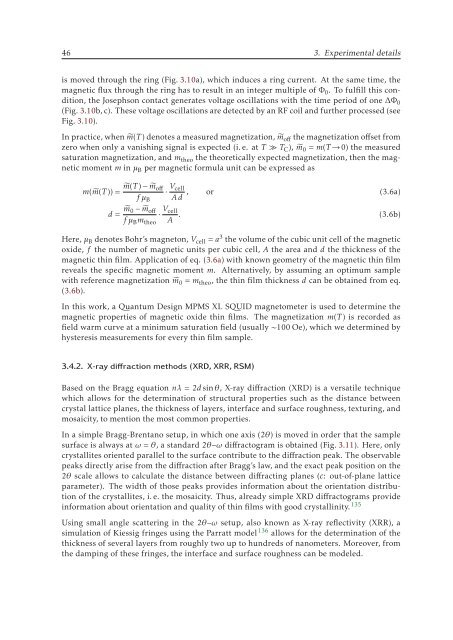
In practice, when ˜m(T ) denotes a measured magnetization, ˜m off the magnetization offset from<br />
zero when only a vanishing signal is expected (i. e. at T ≫ T C ), ˜m 0 = m(T →0) the measured<br />
saturation magnetization, and m theo the theoretically expected magnetization, then the magnetic<br />
moment m in μ B per magnetic formula unit can be expressed as<br />
m( ˜m(T )) = ˜m(T ) − ˜m off<br />
fμ B<br />
d = ˜m 0 − ˜m off<br />
fμ B m theo<br />
· Vcell<br />
A .<br />
· Vcell<br />
, or (3.6a)<br />
Ad<br />
(3.6b)<br />
Here, μ B denotes Bohr’s magneton, V cell = a 3 the volume of the cubic unit cell of the magnetic<br />
oxide, f the number of magnetic units per cubic cell, A the area and d the thickness of the<br />
magnetic thin film. Application of eq. (3.6a) with known geometry of the magnetic thin film<br />
reveals the specific magnetic moment m. Alternatively, by assuming an optimum sample<br />
with reference magnetization ˜m 0 = m theo , the thin film thickness d can be obtained from eq.<br />
(3.6b).<br />
In this work, a Quantum Design MPMS XL SQUID magnetometer is used to determine the<br />
magnetic properties of magnetic oxide thin films. The magnetization m(T ) is recorded as<br />
field warm curve at a minimum saturation field (usually ∼100 Oe), which we determined by<br />
hysteresis measurements for every thin film sample.<br />
3.4.2. X-ray diffraction methods (XRD, XRR, RSM)<br />
Based on the Bragg equation nλ =2d sinθ, X-ray diffraction (XRD) is a versatile technique<br />
which allows for the determination of structural properties such as the distance between<br />
crystal lattice planes, the thickness of layers, interface and surface roughness, texturing, and<br />
mosaicity, to mention the most common properties.<br />
In a simple Bragg-Brentano setup, in which one axis (2θ) is moved in order that the sample<br />
surface is always at ω = θ, a standard 2θ–ω diffractogram is obtained (Fig. 3.11). Here, only<br />
crystallites oriented parallel to the surface contribute to the diffraction peak. The observable<br />
peaks directly arise from the diffraction after Bragg’s law, and the exact peak position on the<br />
2θ scale allows to calculate the distance between diffracting planes (c: out-of-plane lattice<br />
parameter). The width of those peaks provides information about the orientation distribution<br />
of the crystallites, i. e. the mosaicity. Thus, already simple XRD diffractograms provide<br />
information about orientation and quality of thin films with good crystallinity. 135<br />
Using small angle scattering in the 2θ–ω setup, also known as X-ray reflectivity (XRR), a<br />
simulation of Kiessig fringes using the Parratt model 136 allows for the determination of the<br />
thickness of several layers from roughly two up to hundreds of nanometers. Moreover, from<br />
the damping of these fringes, the interface and surface roughness can be modeled.


