75 years of Egokiefer: Tradition and Innovation
75 years of Egokiefer: Tradition and Innovation
75 years of Egokiefer: Tradition and Innovation

Create successful ePaper yourself
Turn your PDF publications into a flip-book with our unique Google optimized e-Paper software.
Steel Technology<br />
Drawn pr<strong>of</strong>iles:<br />
from the idea to the product<br />
The sheet metal door pr<strong>of</strong>ile 735.906/T was announced at BAU 2007 in Munich <strong>and</strong> attracted<br />
considerable interest. The successful pr<strong>of</strong>ile went from idea to manufacture in an exciting manner.<br />
At the start there is a clever idea from development at Forster<br />
Pr<strong>of</strong>ile Systems inspired by market analyses <strong>and</strong> customer<br />
surveys. The idea is «refined», sketched <strong>and</strong> reaches tool<br />
making. There the tube to be used is defined <strong>and</strong> the tools<br />
drawn. The tools are then manufactured, the tubes to be<br />
used welded, <strong>and</strong> the pr<strong>of</strong>iles drawn. The pr<strong>of</strong>iles are then<br />
assembled <strong>and</strong> used to make doors. Sounds simple you could<br />
think. The actual route from the idea to the finished door is<br />
somewhat more complicated:<br />
When practice contradicts theory<br />
The starting point is a finished pr<strong>of</strong>ile shape from which<br />
a tool sequence is defined for the manufacturing process.<br />
For a complex shape, the steel tube used passes through<br />
several stations until the final pr<strong>of</strong>ile is complete. The individual<br />
forming steps must be exactly matched to each other.<br />
Then the exact manufacturing process is defined <strong>and</strong> the<br />
prototypes manufactured. During this activity, theory <strong>and</strong><br />
practice may drift apart. In the case <strong>of</strong> this specific project,<br />
there were problems with the drawing tip during prototype<br />
manufacture. The tips must be matched to the drawing tool<br />
due to the reduction in the cross-section <strong>of</strong> the pr<strong>of</strong>ile shape<br />
produced. The compressed materials cannot, <strong>of</strong> course, be<br />
moved so easily through complex drawing dies. The tips must<br />
be cut in sequence. If too much is cut away, although the entire<br />
piece may pass through the drawing tool the remaining<br />
tip cross-section is insufficient to adsorb the drawing force:<br />
the tip is torn <strong>of</strong>f.<br />
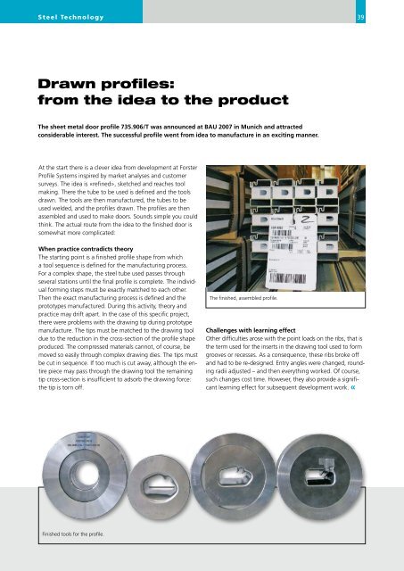
Finished tools for the pr<strong>of</strong>ile.<br />
The finished, assembled pr<strong>of</strong>ile.<br />
39<br />
Challenges with learning effect<br />
Other difficulties arose with the point loads on the ribs, that is<br />
the term used for the inserts in the drawing tool used to form<br />
grooves or recesses. As a consequence, these ribs broke <strong>of</strong>f<br />
<strong>and</strong> had to be re-designed. Entry angles were changed, rounding<br />
radii adjusted – <strong>and</strong> then everything worked. Of course,<br />
such changes cost time. However, they also provide a significant<br />
learning effect for subsequent development work. «