- Page 2:
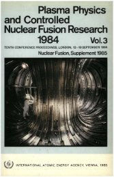
The cover picture shows the inside
- Page 6 and 7:
AFGHANISTAN ALBANIA ALGERIA ARGENTI
- Page 8 and 9:
PLASMA PHYSICS AND CONTROLLED NUCLE
- Page 10 and 11:
EDITORIAL NOTE The Proceedings have
- Page 12 and 13:
A. Kaminaga, T. Kaneko, T. Kato, M.
- Page 14 and 15:
Improved confinement regimes with O
- Page 16 and 17:
Tokamak with strong magnetic field
- Page 18 and 19:
Resonant island divertor experiment
- Page 20 and 21:
Particle removal capabilities of th
- Page 22 and 23:
Inside launch electron cyclotron he
- Page 24 and 25:
T. Hjima, S. Ishida, K. Itami, T. I
- Page 26 and 27:
T. Yamauchi, I. Nakazawa, K. Hasega
- Page 29 and 30:
ARTSIMOVICH MEMORIAL LECTURE C. MAI
- Page 31 and 32:
IAEA-CN-50/A-0 5 ceptible to fast r
- Page 33 and 34:
IAEA-CN-50/A-0 7 fusion power plant
- Page 35 and 36:
FIRST EXPERIMENTS IN TORE SUPRA EQU
- Page 37 and 38:
IAEA-CN-50/A-I-1 11 Supra is the fi
- Page 39 and 40:
IAEA-CN-50/A-I-1 13 poloidal field
- Page 41 and 42:
nee id interfere >res an j-> 1 O E
- Page 43 and 44:
i I •O OJ) — '5 c IS 2 HI 1ZI _
- Page 45 and 46: 5.' ' *[Wbl t. 3. 2. 1. _ _ X IAEA-
- Page 47 and 48: nl 30 .29 .28 .27 26 .25 .24 .23 22
- Page 49 and 50: IAEA-CN-50/A-I-1 However, reasonabl
- Page 51 and 52: IAEA-CN-50/A-I-1 25 will make it po
- Page 53 and 54: IAEA-CN-50/A-I-2 AN OVERVIEW OF TFT
- Page 55 and 56: IAEA-CN-50/A-I-2 29 inner belt limi
- Page 57 and 58: IAEA-CN-50/A-I-2 31 0 10 20 TOTAL P
- Page 59 and 60: 5 DC LU LU 3 - 1 - Q Q A 1 A IAEA-C
- Page 61 and 62: IAEA-CN-50/A-I-2 35 The question ar
- Page 63 and 64: 0.20 0.15 0.10 Rp= 2.45 m a = 0.79
- Page 65 and 66: : . • • 1 IAEA-CN-50/A-I-2 39 1
- Page 67 and 68: LATEST JET RESULTS AND FUTURE PROSP
- Page 69 and 70: Parameter Plasma major radius (Ro)
- Page 71 and 72: 1500 IAEA-CN-50/A-I-3 45 2 4 I, (MA
- Page 73 and 74: IAEA-CN-50/A-I-3 47 3.0 3.5 Major r
- Page 75 and 76: I 15 10 5 0 IAEA-CN-50/A-I-3 49 V \
- Page 77 and 78: IAEA-CN-50/A-I-3 51 Magnetic measur
- Page 79 and 80: 0.8 0.6 IAEA-CN-50/A-I-3 53 -0.2 12
- Page 81 and 82: 10 0.5 Pulse No: 15376 n(He')/ne=1.
- Page 83 and 84: IAEA-CN-50/A-I-3 57 5 10 15 [Pt-dW/
- Page 85 and 86: 10 E X 4 H-mode y 0.2 0.4 0.6 0.8 1
- Page 87 and 88: IAEA-CN-50/A-I-3 61 where V is the
- Page 89 and 90: IAEA-CN-50/A-I-3 63 confinement deg
- Page 91: IAEA-CN-50/A-I-3 65 References [1 ]
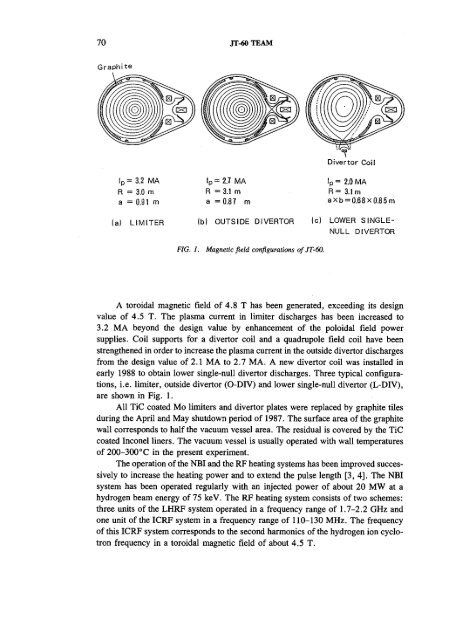
- Page 94 and 95: 68 JT-60 TEAM T. TANAKA, Y. TANAKA,
- Page 98 and 99: 72 JT-60TEAM E5695 0 1 2 3 4 5 6 7
- Page 100 and 101: 74 JT-60TEAM 3 : LIH *3.1HA 2.8HA A
- Page 102 and 103: 76 JT-60TEAM 4.5 5.0 5.5 6.0 6.5 7.
- Page 104 and 105: 78 JT-60TEAM 250 "(a) 200 150 50 n
- Page 106 and 107: 80 JT-60 TEAM The further developme
- Page 109 and 110: STABILITY OF HIGH BETA DISCHARGES I
- Page 111 and 112: IAEA-CN-50/A-II-l 85 a typical plas
- Page 113 and 114: 0.5- 0- 0.8- 0.4- 0.0- IAEA-CN-50/A
- Page 115 and 116: IAEA-CN-50/A-IM 89 absence of the l
- Page 117 and 118: s.o • .5 (a) IAEA-CN-50/A-II-l 91
- Page 119 and 120: IAEA-CN-50/A-II-l 93 stability limi
- Page 121: IAEA-CN-50/A-II-l 95 [6] STAMBAUGH,
- Page 124 and 125: 98 OKABAYASHI et al. PBX-M maximall
- Page 126 and 127: 100 1 .0 .6 .0 -.2 -.4 -.6 1.11 CO
- Page 128 and 129: 102 0.5 OKABAYASHI et al. Indentati
- Page 130 and 131: 104 OKABAYASHI et al. 40 30 I I I I
- Page 132 and 133: 106 OKABAYASHI et al. §1 •a J i
- Page 134 and 135: 108 OKABAYASHI et al. -2 1 • •
- Page 137 and 138: MHD ACTIVITIES AND RELATED IMPURITY
- Page 139 and 140: 0.5 IAEA-CN-50/A-H-3 113 FIG. 1. St
- Page 141 and 142: 0) a. II E IAEA-CN-50/A-H-3 115 1 1
- Page 143 and 144: IAEA-CN-50/A-II-3 117 These observa
- Page 145: 6. CONCLUSIONS IAEA-CN-50/A-II-3 11
- Page 148 and 149:
122 GAO et al. With hydrogen plasma
- Page 150 and 151:
124 GAO et al. P—3.0 r—8.5 SHOT
- Page 152 and 153:
126 GAO et al. a) M >
- Page 154 and 155:
128 GAO et al. 0.6 0.3 0.0 50 100 r
- Page 157 and 158:
SUPERLOW DENSITY EXPERIMENT ON HT-6
- Page 159 and 160:
IAEA-CN-50/A-n-S-l 133 (b) Hard X-r
- Page 161 and 162:
IAEA-CN-SO/A-n-5-l 135 0 0.2 0.4 0:
- Page 163 and 164:
IAEA-CN-50/A-D-5-2 INVESTIGATION OF
- Page 165 and 166:
0.14 0.10 0.09 0.08 0.05 0.04 0.03
- Page 167 and 168:
TABLE I. REDUCTION OF Xe (m 2 -s')
- Page 169:
IAEA-CN-50/A-II-5-2 143 (3) The lin
- Page 172 and 173:
146 FUSSMANN et al. Abstract IMPROV
- Page 174 and 175:
148 FUSSMANN et al. 150- 100- 50- 0
- Page 176 and 177:
150 FUSSMANN et al. UJ 100- 50- + 2
- Page 178 and 179:
152 FUSSMANN et al. In both regimes
- Page 180 and 181:
154 FUSSMANN et al. reduced. With c
- Page 182 and 183:
156 FUSSMANN et al. and consequentl
- Page 185 and 186:
THE JET H-MODE AT HIGH CURRENT AND
- Page 187 and 188:
IAEA-CN-50/A-IH-2 achieve an H-mode
- Page 189 and 190:
6.0 40 2.0 (a) 0l=. 5.0 (c) 0 Pulse
- Page 191 and 192:
IAEA-CN-50/A-III-2 165 reduced in t
- Page 193 and 194:
IAEA-CN-50/A-HI-2 167 near the firs
- Page 195 and 196:
IAEA-CN-50/A-III-2 169 plasmas with
- Page 197 and 198:
I 3s H-mode 8
- Page 199 and 200:
IAEA-CN-50/A-HI-2 173 The steep tem
- Page 201 and 202:
IAEA-CN-50/A-III-2 175 available),
- Page 203 and 204:
IAEA-CN-50/A-III-2 177 (xi0 19 m 3
- Page 205 and 206:
IAEA-CN-50/A-III-2 179 APPENDIX I T
- Page 207:
IAEA-CN-50/A-IH-2 181 [16] Bishop,
- Page 210 and 211:
184 ZARNSTORFT et al. Abstract TRAN
- Page 212 and 213:
186 ZARNSTORFF et al. X-ray spectro
- Page 214 and 215:
188 ZARNSTORFF et al. 8 CM e CM E 2
- Page 216 and 217:
190 ZARNSTORFF et al. 1.5 2.0 2.5 n
- Page 219 and 220:
IAEA-CN-50/A-III-4 ENERGY CONFINEME
- Page 221 and 222:
o O •
- Page 223 and 224:
0.3 0.2- 0.1- 0.0 0.8 0.6 0.4 0.2 0
- Page 225 and 226:
00 d f CM I- CQ i o o o IAEA-CN-50/
- Page 227 and 228:
E m F LU LJU Z o N_ CE UU o / UJ q
- Page 229 and 230:
IAEA-CN-50/A-m-4 203 The TB values
- Page 231:
IAEA-CN-50/A-HM 205 [7] OHYABU, N.,
- Page 234 and 235:
208 SUZUKI et al. favourable in a c
- Page 236 and 237:
210 SUZUKI etal. As the neutral bea
- Page 238 and 239:
212 SUZUKI et al. 3. FOUR-PELLET IN
- Page 241 and 242:
HEATING OF PEAKED DENSITY PROFILES
- Page 243 and 244:
Yd o g a> - c 4 _n ...— 0) n 12 t
- Page 245 and 246:
1.3 I" 1 |03 C 0.5 i: 12 8 4 n - Te
- Page 247 and 248:
IAEA-CN-50/A-IV-l 221 1 2 3 Q,_-2ff
- Page 249 and 250:
2 q(o) 1- 10 1 U • O • IAEA-CN-
- Page 251 and 252:
0.3 f0.2 1 5" 0.1 IAEA-CN-50/A-IV-l
- Page 253 and 254:
IAEA-CN-50/A-IV-l 227 APPENDIX I TH
- Page 255 and 256:
IAEA-CN-50/A-IV-2 PELLET INJECTION
- Page 257 and 258:
3 - 2 - 1 - IAEA-CN-50/A-IV-2 231 1
- Page 259 and 260:
0 FIG. 4. ONI O £ at o ID c IC 15
- Page 261 and 262:
IAEA-CN-50/A-IV-2 0.35 MW 2.6 MW Ga
- Page 263:
IAEA-CN-50/A-IV-2 237 finement. The
- Page 266 and 267:
240 AZIZOV et al. TABLE I. TSP PARA
- Page 268 and 269:
242 AZIZOV et al. 65 75 85 95 105 1
- Page 270 and 271:
244 AZIZOV et al. 30 40 50 60 Ip =
- Page 273 and 274:
HIGH TEMPERATURE EXPERIMENTS AND FU
- Page 275 and 276:
IAEA-CN-50/A-IV-4 249 FIG. 1. Data
- Page 277 and 278:
P ICRHV 2 IAEA-CN-50/A-IV-4 251 FIG
- Page 279 and 280:
IAEA-CN-SO/AIV-4 253 FIG. 4. (a) Di
- Page 281:
IAEA-CN-50/A-IV-4 255 The fusion pe
- Page 284 and 285:
258 STRACHAN et al. - Z - 1, Steady
- Page 286 and 287:
260 STRACHAN et al. 10' 10' Classic
- Page 288 and 289:
262 STRACHAN et al. _ 1 s 10* I : 1
- Page 291 and 292:
ENERGY CONFINEMENT WITH AUXILIARY H
- Page 293 and 294:
E6950(Bi=4.0T) E6956(Bt = 2.7T) °4
- Page 295 and 296:
E7558 • IMPROVED 5 6 TIME (S) IAE
- Page 297 and 298:
7.0 E - 1 0.0 7.0 0.0 =— \ n; - T
- Page 299:
IAEA-CN-50/A-V-1 273 [9] SHIMOMURA,
- Page 302 and 303:
276 ASHRAF et al. However, the conv
- Page 304 and 305:
278
- Page 306 and 307:
280 ASHRAF et al. Modulation amplit
- Page 308 and 309:
282 KIMet al. (a) (b) 410 420 TIME
- Page 310 and 311:
284 KIM et al. (b) o 3
- Page 312 and 313:
286 KIM et ah In summary, we observ
- Page 314 and 315:
288 KAWAHATA et al. TEXT tokamak, t
- Page 316 and 317:
290 KAWAHATA et al. ^ 30 °- S-200.
- Page 318 and 319:
292 KAWAHATA et al. 0 6 12 18 24 ra
- Page 320 and 321:
294 WOOTTON et al. 1. Particle tran
- Page 322 and 323:
296 10' N 10° E gio- 1 O (a) 10" 0
- Page 324 and 325:
298 WOOTTON et al. ne=3xl0 19 m- 3
- Page 326 and 327:
300 ZURRO et al. FIG. 1. Variation
- Page 328 and 329:
302 ZURRO et al. Mo) 6 (10"cm- 3 )
- Page 330 and 331:
304 ZURRO et al. -140 50 100 f(kHz)
- Page 333 and 334:
TRANSPORT STUDIES ON TFTR UTILIZING
- Page 335 and 336:
IAEA-CN-50/A-V-4 309 uses the TRANS
- Page 337 and 338:
5 g 30 20 < 2.0 Q § 1.0 i 0.5 10 1
- Page 339 and 340:
IAEA-CN-50/A-V-4 313 the laser-blow
- Page 341 and 342:
IAEA-CN-S0/A-V-4 315 on working gas
- Page 343 and 344:
I0 7 ! 10' 1.8 IAEA-CN-50/A-V-4 317
- Page 345 and 346:
IAEA-CN-50/A-V-4 319 The difference
- Page 347:
IAEA-CN-50/A-V-4 321 [12] RADEZTSKY
- Page 350 and 351:
324 DONNE et al. E CO o FIG. 1. Sho
- Page 352 and 353:
326 DONNE et al. 350 300 250 200 15
- Page 354 and 355:
328 DONNE et al. 1.0 0.8 - 0.6 - t
- Page 357 and 358:
RECENT TEXTOR RESULTS TEXTOR TEAM (
- Page 359 and 360:
IAEA-CN-50/A-VI-l 333 line-radiatio
- Page 361 and 362:
IAEA-CN-50/A-VI-l 335 These measure
- Page 363 and 364:
q(r] 3- 2- 1- - IAEA-CN-50/A-VI-l 3
- Page 365 and 366:
IAEA-CN-50/A-VI-l 339 FIG. 4. Sawto
- Page 367 and 368:
IAEA-CN-S0/A-VI-2-1 RESONANT ISLAND
- Page 369 and 370:
IAEA-CN-50/A-VI-2-1 343 • «• >
- Page 371:
IAEA-CN-50/A-VI-2-1 345 tons. This
- Page 374 and 375:
348 EVANS et al. JIPP T-IIU ( minor
- Page 376 and 377:
350 EVANS et al. FIG. 3. High speed
- Page 378 and 379:
352 EVANS et al. REFERENCES [1] KAR
- Page 380 and 381:
354 BAKOS et al. The radiation of t
- Page 382 and 383:
356 BAKOS et al. < + s 5 2 1 5 2 10
- Page 384 and 385:
358 BAKOS et al. REFERENCES [1] BAK
- Page 386 and 387:
360 STfiCKEL et al. A quantitative
- Page 388 and 389:
362 STOCKEL et al. This and other f
- Page 390 and 391:
364 STOCKEL et al. 15 I 10 "" 5 0 (
- Page 393 and 394:
GLOBAL POWER BALANCE AND LOCAL HEAT
- Page 395 and 396:
0.5 1 r. (s> Goldston IAEA-CN-50/A-
- Page 397 and 398:
IAEA-CN-50/A-VH-l 371 Separate Elec
- Page 399 and 400:
IAEA-CN-50/A-VII-l 373 4. SIMULATIO
- Page 401 and 402:
6. CONCLUSIONS IAEA-CN-50/A-VII-l 3
- Page 403 and 404:
SAWTOOTH ACTIVITY AND CURRENT DENSI
- Page 405 and 406:
-0.6 (keV) 6.6 6.4 6.2 6.0 5.8 IAEA
- Page 407 and 408:
IAEA-CN-50/A-VII-2 381 #15697 . 0 1
- Page 409 and 410:
IAEA-CN-50/A-VII-2 383 radius. In a
- Page 411:
IAEA-CN-50/A-VH-2 385 [11] Goldston
- Page 414 and 415:
388 NAGAYAMA et al. of the magnetic
- Page 416 and 417:
390 NAGAYAMA et al. RECONNECTION RE
- Page 418 and 419:
392 NAGAYAMA et al. m/n=2/1 island
- Page 421 and 422:
STABILITY OF TFTR PLASMAS IAEA-CN-5
- Page 423 and 424:
IAEA-CN-50/A-VII-4 397 the electron
- Page 425 and 426:
9 8 — 7 6 5 4 - 3 2 X • * • i
- Page 427 and 428:
0.5 ' 0.4 0.3 - 3 0.2 0.1 - 0 —r"
- Page 429 and 430:
0.4 0.3 0.2 0.1 n IAEA-CN-50/A-VH-4
- Page 431 and 432:
Ip(MA) 0.85 0.89 0.9 0.9 1.4 IAEA-C
- Page 433:
IAEA-CN-50/A-VH-4 407 ACKNOWLEDGMEN
- Page 436 and 437:
410 AGIM et al. , , , , I , , , .,
- Page 438 and 439:
412 AGIM et al. to diminish and the
- Page 440 and 441:
414 AGIM et al. Hence, the preventi
- Page 442 and 443:
416 MAUELetal. Small tokamak plasma
- Page 444 and 445:
418 MAUELetal. 3. Mode structure of
- Page 446 and 447:
420 100- 350 MAUEL et al. RAOIUS (c
- Page 449 and 450:
STUDY OF PLASMA MHD STABILITY IN T-
- Page 451 and 452:
1.5 _ 1.0 >
- Page 453 and 454:
20 £ 15 - " 10 II 5 5 — ECH IAEA
- Page 455 and 456:
200 - IAEA-CN-S0/A-Vn-7 429 I I I I
- Page 457 and 458:
60 40 20 n / l IAEA-CN-S0/A-VII-7 4
- Page 459 and 460:
LU 30 - 20 - 10 - IAEA-CN-50/A-V1I-
- Page 461 and 462:
as if 200 - 100 -- 20 - I 10 - 15
- Page 463 and 464:
RELAXATION OF q PROFILE IN A HIGH B
- Page 465 and 466:
0 0.5 1.0 IAEA-CN-50/A-VII-8 439 .
- Page 467 and 468:
0 6 12 (Wall) r(cm) IAEA-CN-50/A-VH
- Page 469:
5. CONCLUSIONS IAEA-CN-50/A-VH-8 44
- Page 472 and 473:
446 HENDERetal. An alternative meth
- Page 474 and 475:
448 HENDER et al. and Jdriven(max)
- Page 476 and 477:
450 HENDER et al. TJ :? Island V 6
- Page 479 and 480:
IAEA-CN-50/A-VII-10 PARTICLE REMOVA
- Page 481 and 482:
IAEA-CN-50/A-VH-10 455 3. POLOIDAL
- Page 483 and 484:
X > o S 6 U- 2- 0 160 • 80 0 1 0.
- Page 485 and 486:
IAEA-CN-S0/A-VH-10 459 between scoo
- Page 487 and 488:
THE ROLE OF LIMITERS AND WALLS IN I
- Page 489 and 490:
Shine through IAEA-CN-50/A-VH-ll 46
- Page 491 and 492:
3 01 £ "c t=! o E c 12 10 8 6 4 2
- Page 493 and 494:
THE PLASMA BOUNDARY IN JET IAEA-CN-
- Page 495 and 496:
o x CO o 3.0 2.0 .2-0.5 'in c 0.3 1
- Page 497 and 498:
1 10" IAEA-CN-50/A-VI1-12 LCFS LCFS
- Page 499 and 500:
o •£ 0.15 'o = 0.05 C O J3 o 0.0
- Page 501:
IAEA-CN-50/A-VIM2 475 densities, bu
- Page 504 and 505:
478 LEONOV et al. 2. INSTALLATION A
- Page 506 and 507:
480 LEONOV et al. &r (cm) 0.2 -0.2
- Page 508 and 509:
482 LEONOV et al. Uo, at constant p
- Page 510 and 511:
484 CHEETHAM et al. We present simu
- Page 512 and 513:
486 CHEETHAM et al. 0 20 40 60 30 1
- Page 514 and 515:
488 CHEETHAM et al. o LU 3.0 2.8
- Page 516 and 517:
490 CHEETHAM et al. sior CO 111 c o
- Page 518 and 519:
492 CHEETHAM et al. reported from o
- Page 521 and 522:
IAEA-CN-S0/A-Vn-15 EXPERIMENTAL RES
- Page 523 and 524:
IAEA-CN-50/A-VII-15 497 800 (a) _ -
- Page 525 and 526:
IAEA-CN-50/A-VII-15 499 formation.
- Page 527 and 528:
300 4X10' 3 - IAEA-CN-50/A-VII-15 5
- Page 529:
CONCLUSION IAEA-CN-50/A-VU-1S 503 W
- Page 532 and 533:
506 KIKUCH1 et al. 1. INTRODUCTION
- Page 534 and 535:
508 KIKUCHI et al. 1.0 o.s 1 — -
- Page 536 and 537:
510 KIKUCHIetal. REFERENCES [1] ZAR
- Page 539 and 540:
STUDY OF DENSITY LIMIT AND LOW q(aL
- Page 541 and 542:
IAEA-CN-50/E-I-l-l 515 1 2 3 4 5 ne
- Page 543 and 544:
/ / IAEA-CN-50/E-I-l-l 517 / / / /
- Page 545 and 546:
(J n 3 o ? 2 i o ' 1 IAEA-CN-50/E-M
- Page 547 and 548:
0.03 - 0.02 - 0.01 - IAEA-CN-50/E-I
- Page 549 and 550:
CO u CO "o IC 7 - 6 — 5 - 4 - 3 1
- Page 551:
IAEA-CN-50/E-I-l-l REFERENCES 52 5
- Page 554 and 555:
528 PRATER et al. 1. INTRODUCTION E
- Page 556 and 557:
530 PRATER et al. 0.8 0.6 0.4 0.2 n
- Page 558 and 559:
532 PRATER et al. 1.5 x 10 19 m~ 3
- Page 560 and 561:
534 PRATER et al. 10 1 0.75 0.25 0.
- Page 562 and 563:
536 PRATER et al. added to 1.25 MW
- Page 564 and 565:
538 PRATER et al. 2.0 1.5 1.0 0.5 /
- Page 567 and 568:
INSIDE LAUNCH ELECTRON CYCLOTRON HE
- Page 569 and 570:
0-20 0-15 a CO. 0-10 0-05 0-0 5S g.
- Page 571 and 572:
IAEA-CN-50/E-I-3 545 0.25 • (a) 1
- Page 573 and 574:
IAEA-CN-50/E-I-3 547 A/3 deduced fr
- Page 575:
IAEA-CN-50/E-I-3 549 ECRH phases as
- Page 578 and 579:
552 MOTOJIMA et al. ICRF and plasma
- Page 580 and 581:
554 MOTOJIMA et al. (a) 0.6SneS0.9x
- Page 582 and 583:
556 MOTOJIMA et al. 0 20 W 60 80 10
- Page 584 and 585:
558 5 4 3 2 1 0 60 40 20 0 la) cuto
- Page 586 and 587:
560 MOTOJIMA et al. 3 0.005 0 0.2 0
- Page 589 and 590:
RF CURRENT DRIVE AND MHD INSTABILIT
- Page 591 and 592:
IAEA-CN-50/E-I-5 565 80 PEC
- Page 593 and 594:
of x o o i L_ t IAEA-CN-50/E-I-5 56
- Page 595 and 596:
IAEA-CN-50/E-I-5 569 FIG. 5. Contou
- Page 597 and 598:
HEATING AND CONFINEMENT STUDIES WIT
- Page 599 and 600:
R 6 IAEA-CN-50/E-IM 0.5 10 1.5 Ne(r
- Page 601 and 602:
IAEA-CN-50/E-II-l FIG. 3. Total rad
- Page 603 and 604:
IAEA-CN-50/E-II-l 577 1.0 2.0 Time
- Page 605 and 606:
IAEA-CN-50/E-II-l 579 TABLE I. SUMM
- Page 607 and 608:
6. SAWTOOTH BEHAVIOUR IAEA-CN-50/E-
- Page 609 and 610:
IAEA-CN-50/E-II-2 LONG PULSE HIGH P
- Page 611 and 612:
IAEA-CN-50/E-II-2 585 23996 2 3 0 U
- Page 613 and 614:
IAEA-CN-50/E-II-2 587 TABLE I. a) C
- Page 615 and 616:
t a ce> 03 E cs o. otal 100 90 80 7
- Page 617 and 618:
IAEA-CN-50/E-H-2 591 and confinemen
- Page 619 and 620:
IAEA-CN-50/E-n-3 EXPERIMENTAL AND T
- Page 621 and 622:
§ 1PUTUDE ( $ #•14613 200 (a) 18
- Page 623 and 624:
IAEA-CN-50/E-II-3 597 The results o
- Page 625 and 626:
to V. (a)' • \ \ \ \ \ \ w \'\ \\
- Page 627 and 628:
IAEA-CN-50/E-II-3 601 cccurs progre
- Page 629:
IAEA-CN-50/E-II-3 603 [5] CAMPBELL,
- Page 632 and 633:
606 FUJII et al. 1. INTRODUCTION Se
- Page 634 and 635:
608 140 " (0,0) PIC= l~ 3 MW 120 '
- Page 636 and 637:
610 FUJII et al. ACKNOWLEDGEMENTS T
- Page 638 and 639:
612 BATCHELOR et al. resolves this
- Page 640 and 641:
614 BATCHELOR et al. •J5 1
- Page 642 and 643:
616 BATCHELOR et al. to match asymp
- Page 644 and 645:
618 BATCHELOR et al. of T, R, and C
- Page 646 and 647:
620 BATCHELOR et al. [3] SMITHE, D.
- Page 648 and 649:
622 USHIGUSA et al. 1. INTRODUCTION
- Page 650 and 651:
624 USHIGUSA et al. at f = 1.74 GHz
- Page 652 and 653:
626 USHIGUSA et al. BT (T) (ms) ao
- Page 654 and 655:
628 USHIGUSA et al. [2] JT-60 TEAM,
- Page 656 and 657:
630 ITOH et al. , Breakdown 20 40 6
- Page 658 and 659:
632 ITOH et al. 1.0 20 30 40 50 60
- Page 660 and 661:
634 ITOH et al. 30 |20 a "" 10 n H=
- Page 662 and 663:
636 ITOH et al. REFERENCES [1] ITOH
- Page 664 and 665:
638 ALLADIO et al. generation of hi
- Page 666 and 667:
640 ALLADIO et al. 4 T (keV) 3 2 -
- Page 668 and 669:
642 ALLADIO et al. 3 ID 10 2 10' 10
- Page 671 and 672:
IAEA-CN-50/E-ID-4 LOWER HYBRID WAVE
- Page 673 and 674:
1000 - 500 1001— o — 2 35 IAEA-
- Page 675 and 676:
10 10* 10 10 IAEA-CN-50/E-HI-4 649
- Page 677 and 678:
IAEA-CN-50/E-III-4 651 density of t
- Page 679 and 680:
IAEA-CN-50/E-IU-4 653 I I I I I I F
- Page 681 and 682:
CURRENT DRIVE AND CONFINEMENT OF AN
- Page 683 and 684:
1.0 -0.5 o - - 4.0 IAEA-CN-50/E-III
- Page 685 and 686:
IAEA-CN-50/E-III-5 659 TABLE I. SUM
- Page 687 and 688:
IAEA-CN-SO/E-in-S 661 0.4 RADIUS (m
- Page 689 and 690:
10' Convection Dominates IAEA-CN-50
- Page 691 and 692:
IAEA-CN-50/E-III-5 665 versus unbal
- Page 693:
IAEA-CN-50/E-III-5 667 [11] ZARNSTO
- Page 696 and 697:
670 SIMONEN et al. Neutral beam cur
- Page 698 and 699:
672 SIMONEN et al. 1.6 2.0 FIG. 3.
- Page 700 and 701:
674 SIMONEN et al. MHD modes, obser
- Page 702 and 703:
676 SIMONEN et al. toroidal drift o
- Page 704 and 705:
678 SIMONEN et al. occurs near the
- Page 707 and 708:
NEW CURRENT DRIVE AND CONFINEMENT T
- Page 709 and 710:
IAEA-CN-50/E-III-7 683 is typically
- Page 711 and 712:
IAEA-CN-S0/E-III-7 685 plasma beta
- Page 713 and 714:
IAEA-CN-50/E-III-7 687 The equilibr
- Page 715:
IAEA-CN-50/E-III-7 689 [8] McGUIRE,
- Page 718 and 719:
692 100 a 10- 0.1 WILSON et al. •
- Page 720 and 721:
694 WILSON et al. 3. Plasma Heating
- Page 722 and 723:
696 WILSON et al. I 3 i - • / Tim
- Page 725 and 726:
INVESTIGATION OF ICRH ON THE TUMAN-
- Page 727 and 728:
~x o X •9to 12 1 11 10 180 s - 12
- Page 729 and 730:
400 - 300 - 200 - I 100 - 35 / 1 ,
- Page 731 and 732:
5 - IAEA-CN-50/E-IV-2 r (cm) FIG. 7
- Page 733 and 734:
IAEA-CN-50/E-IV-3 CONVERSION AND CY
- Page 735 and 736:
IAEA-CN-50/E-IV-3 709 bution, e(j,
- Page 737 and 738:
IAEA-CN-S0/E-IV-3 711 FIG. 3. kxPd
- Page 739 and 740:
IAEA-CN-50/E-IV-3 713 3. NON-LOCAL
- Page 741 and 742:
x exp | ds" ' u ' x -oosgn u d fiV2
- Page 743 and 744:
IAEA-CN-50/E-IV-3 717 x If {sin i [
- Page 745:
IAEA-CN-5O/E-IV-3 719 2. A non-loca
- Page 748 and 749:
722 MOREAU et al. =t _» Here, K is
- Page 750 and 751:
724 MOREAU et al. FIG. 1. Modulus o
- Page 752 and 753:
726 MOREAU et al. REFERENCES [1] MA
- Page 754 and 755:
728 YASAKA et al. 2. EFFICIENT PLAS
- Page 756 and 757:
730 YASAKA et al. '£ 1 0.5 0 4 Pne
- Page 758 and 759:
732 YASAKA et al. WT-3 1 2 Q,f C 10
- Page 760 and 761:
734 invi p o p p •^ CJ -^ o IO o
- Page 762 and 763:
736 YAMAMOTO et al. (A) OJ — o (A
- Page 764 and 765:
738 YAMAMOTO et al. of Tsx =1.5 keV
- Page 766 and 767:
740 PEREVERZEV current drive produc
- Page 768 and 769:
742 PEREVERZEV 300 - - 150 ne (10 1
- Page 770 and 771:
744 PEREVERZEV 0.2- -0.2- 0.1X10 19
- Page 772 and 773:
746 PEREVERZEV The dependences of l
- Page 774 and 775:
748 PORKOLAB et al. ASPECT RATIO FI
- Page 776 and 777:
750 PORKOLAB et al. 1.0 _, 0.8 1 0.
- Page 778 and 779:
752 PORKOLAB et al. X D E o Q_ 1.8
- Page 780 and 781:
754 LUO et al. - o £ 3 §. II Ml "
- Page 782 and 783:
756 LUO et al. 20 10 ATe ( 1 m11 1
- Page 785 and 786:
IAEA-CN-50/E-IV-10 MICROWAVE HEATIN
- Page 787 and 788:
n MCPAT _ Analysis IAEA-CN-50/E-IV-
- Page 789 and 790:
IAEA-CN-50/E-IV-10 763 3. QUASI-LIN
- Page 791 and 792:
IAEA-CN-50/E-IV-10 765 In the limit
- Page 793 and 794:
IAEA-CN-50/E-IV-ll SECOND ELECTRON
- Page 795 and 796:
IAEA-CN-50/E-IV-ll 769 FIG. ]. Real
- Page 797 and 798:
-0.2 IAEA-CN-50/E-IV-ll 771 FIG. 3.
- Page 799:
IAEA-CN-50/E-IV-ll 773 gests that i
- Page 802:
HOW TO ORDER IAEA PUBLICATIONS An e