SERVICE MANUAL MR-G57N-T-NZ - B.d.t.
SERVICE MANUAL MR-G57N-T-NZ - B.d.t.
SERVICE MANUAL MR-G57N-T-NZ - B.d.t.

You also want an ePaper? Increase the reach of your titles
YUMPU automatically turns print PDFs into web optimized ePapers that Google loves.
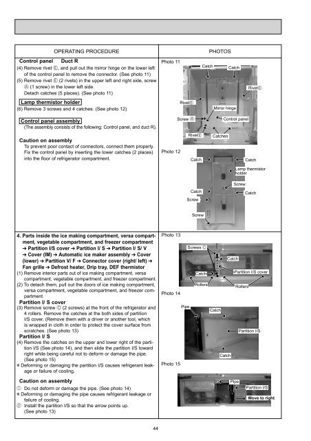
OPERATING PROCEDURE PHOTOS<br />
Control panel Duct R<br />
(4) Remove rivet , and pull out the mirror hinge on the lower left<br />
of the control panel to remove the connector. (See photo 11)<br />
(5) Remove rivet (2 rivets) in the upper left and right side, screw<br />
(1 screw) in the lower left side.<br />
Detach catches (5 places). (See photo 11)<br />
Lamp thermistor holder<br />
(6) Remove 3 screws and 4 catches. (See photo 12)<br />
Control panel assembly<br />
(The assembly consists of the following: Control panel, and duct R).<br />
Caution on assembly<br />
To prevent poor contact of connectors, connect them properly.<br />
Fix the control panel by inserting the lower catches (2 places)<br />
into the floor of refrigerator compartment.<br />
4. Parts inside the ice making compartment, versa compartment,<br />
vegetable compartment, and freezer compartment<br />
Partition I/S cover Partition I/ S Partition I/ S/ V<br />
Cover (IM) Automatic ice maker assembly Cover<br />
(lower) Partition V/ F Connector cover (right/ left)<br />
Fan grille Defrost heater, Drip tray, DEF thermistor<br />
(1) Remove interior parts out of ice making compartment, versa<br />
compartment, vegetable compartment, and freezer compartment.<br />
(2) To detach them, pull out the doors of ice making compartment,<br />
versa compartment, vegetable compartment, and freezer compartment.<br />
Partition I/ S cover<br />
(3) Remove screw (2 screws) at the front of the refrigerator and<br />
4 rollers. Remove the catches at the both sides of partition<br />
I/S cover. (Remove them with a driver or another tool, which<br />
is wrapped in cloth in order to protect the cover surface from<br />
scratches. (See photo 13)<br />
Partition I/ S<br />
(4) Remove the catches on the upper and lower right of the partition<br />
I/S (See photo 14), and then slide the partition I/S toward<br />
right while being careful not to deform or damage the pipe.<br />
(See photo 15)<br />
Deforming or damaging the partition I/S causes refrigerant leakage<br />
or failure of cooling.<br />
Caution on assembly<br />
Do not deform or damage the pipe. (See photo 14)<br />
Deforming or damaging the pipe causes refrigerant leakage or<br />
failure of cooling.<br />
Install the partition I/S so that the arrow points up.<br />
(See photo 13)<br />
44<br />
Photo 11<br />
Photo 12<br />
Photo 13<br />
Photo 14<br />
Photo 15<br />
Rivet<br />
Screw<br />
Pipe<br />
Rivet<br />
Catch<br />
Screw<br />
Screw<br />
Screws<br />
Catch<br />
Catch<br />
Rollers<br />
Mirror hinge<br />
Catches<br />
A<br />
r<br />
r<br />
o<br />
w<br />
Catch<br />
Control panel<br />
Catch<br />
Catch<br />
Catch<br />
Rivet<br />
Catch Catch<br />
Lamp thermistor<br />
holder<br />
Screw<br />
Catch<br />
Partition I/S cover<br />
Pipe<br />
Rollers<br />
Partition I/S<br />
Partition I/S<br />
Move to right