SEC-400series - Shavo Technologies
SEC-400series - Shavo Technologies
SEC-400series - Shavo Technologies

Create successful ePaper yourself
Turn your PDF publications into a flip-book with our unique Google optimized e-Paper software.
03<br />
GAS<br />
What is a mass flow controller?<br />
A mass flow controller is a device that measures and controls the mass flow<br />
rate of fluids. Flow rate measurement of fluids generally uses either volumetric<br />
or mass flow rate. With volumetric flow rate measurement, the ambient<br />
temperature and pressure of the fluid being measured affect the volume, and<br />
accurate measurement requires correcting for any changes in the environment<br />
during the measurement process. With mass flow rate measurement, on the<br />
other hand, the mass (weight) of the fluid is measured, so there is no need to<br />
correct for changes in the measurement environment. Mass flow controllers<br />
are widely used as flow rate controllers in processes that demand high<br />
precision flow rate measurement and control, such as the semiconductor<br />
manufacturing process. HORIBA STEC offers a varied lineup of mass flow<br />
controllers, including digital models that feature CPUs and are compatible<br />
with DeviceNet, to suit every customer’s needs.<br />
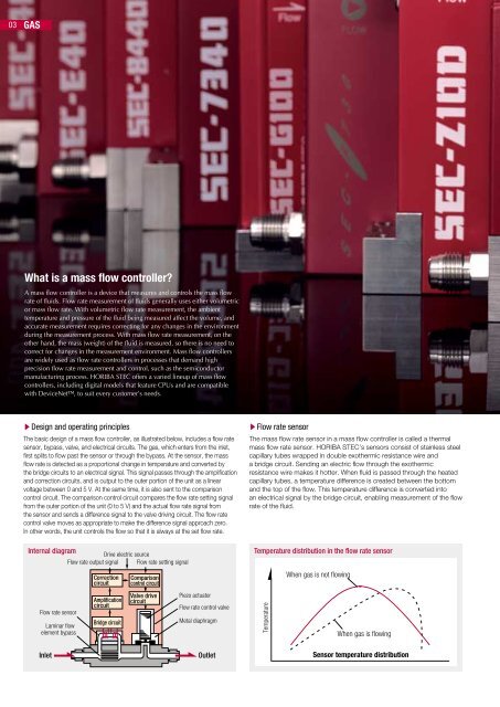
sDesign and operating principles<br />
The basic design of a mass flow controller, as illustrated below, includes a flow rate<br />
sensor, bypass, valve, and electrical circuits. The gas, which enters from the inlet,<br />
first splits to flow past the sensor or through the bypass. At the sensor, the mass<br />
flow rate is detected as a proportional change in temperature and converted by<br />
the bridge circuits to an electrical signal. This signal passes through the amplification<br />
and correction circuits, and is output to the outer portion of the unit as a linear<br />
voltage between 0 and 5 V. At the same time, it is also sent to the comparison<br />
control circuit. The comparison control circuit compares the flow rate setting signal<br />
from the outer portion of the unit (0 to 5 V) and the actual flow rate signal from<br />
the sensor and sends a difference signal to the valve driving circuit. The flow rate<br />
control valve moves as appropriate to make the difference signal approach zero.<br />
In other words, the unit controls the flow so that it is always at the set flow rate.<br />
sFlow rate sensor<br />
The mass flow rate sensor in a mass flow controller is called a thermal<br />
mass flow rate sensor. HORIBA STEC’s sensors consist of stainless steel<br />
capillary tubes wrapped in double exothermic resistance wire and<br />
a bridge circuit. Sending an electric flow through the exothermic<br />
resistance wire makes it hotter. When fluid is passed through the heated<br />
capillary tubes, a temperature difference is created between the bottom<br />
and the top of the flow. This temperature difference is converted into<br />
an electrical signal by the bridge circuit, enabling measurement of the flow<br />
rate of the fluid.<br />
Internal diagram<br />
Drive electric source<br />
Temperature distribution in the flow rate sensor<br />
Flow rate output signal Flow rate setting signal<br />
Flow rate sensor<br />
Laminar flow<br />
element bypass<br />
Correction<br />
circuit<br />
Amplification<br />
circuit<br />
Bridge circuit<br />
Comparison<br />
control circuit<br />
Valve drive<br />
circuit<br />
Piezo actuator<br />
Flow rate control valve<br />
Metal diaphragm<br />
Inlet Outlet<br />
Temperature<br />
When gas is not flowing<br />
When gas is flowing<br />
Sensor temperature distribution