SEC-400series - Shavo Technologies
SEC-400series - Shavo Technologies
SEC-400series - Shavo Technologies

You also want an ePaper? Increase the reach of your titles
YUMPU automatically turns print PDFs into web optimized ePapers that Google loves.
39<br />
LIQUID<br />
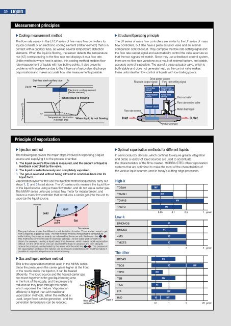
Measurement principles<br />
sCooling measurement method<br />
The flow rate sensor in the LF/LV series of fine mass flow controllers for<br />
liquids consists of an electronic cooling element (Peltier element) that is in<br />
contact with a capillary tube, as well as several temperature detection<br />
elements. When the liquid is flowing, the sensor detects the temperature<br />
rise (∆T) corresponding to the flow rate and displays it as a flow rate.<br />
Unlike methods where heat is added, this cooling method enables flow<br />
rate measurement of liquids with low boiling points. It also prevents<br />
problems with interference due to the influence of secondary discharge<br />
(vaporization) and makes accurate flow rate measurements possible.<br />
Temperature (°C)<br />
Liquid<br />
Stainless steel capillary tube Ts<br />
∆T<br />
Principle of vaporization<br />
sInjection method<br />
Pressure<br />
Solid<br />
Temperature distribution<br />
in sensor area<br />
Triple<br />
point<br />
Electronic cooling element<br />
(Peltier element)<br />
When liquid is flowing<br />
Liquid<br />
When liquid is not flowing<br />
The following list covers the major steps involved in vaporizing a liquid<br />
source and supplying it to the process chamber.<br />
1. The liquid source's flow rate is measured, and the amount of liquid is<br />
feedback controlled by the valve.<br />
2. The liquid is instantaneously and completely vaporized.<br />
3. The gas is released without being allowed to condense back into its<br />
liquid form.<br />
Vaporization systems that use the injection method sequentially carry out<br />
steps 1, 2, and 3 listed above. The VC series units measure the liquid flow<br />
of the liquid source using a mass flow meter, and do not use a carrier gas.<br />
The MI/MV series units use a mass flow meter for measurement, and<br />
feature a mass flow controller that introduces a carrier gas into the unit to<br />
vaporize the liquid source.<br />
Temperature<br />
The graph above shows the different possible states of matter. There are two ways to get<br />
from a liquid to a gaseous state. The first method involves increasing the temperature<br />
while holding the pressure steady, as indicated by the arrow with the broken line ( ).<br />
This method is commonly used in everyday settings—to boil water and convert it to<br />
steam, for example. Heating a liquid takes time, however, which makes rapid vaporization<br />
difficult. On the other hand, one can also heat the liquid in advance and then abruptly<br />
reduce the pressure, as illustrated by the arrow with the solid line ( ). The pressure in<br />
the vaporization section of the injector can be reduced instantaneously, and this makes it<br />
possible to vaporize a liquid source instantaneously.<br />
sGas and liquid mixture method<br />
Gas<br />
This is the vaporization method used in the MI/MV series.<br />
Since the pressure on the carrier gas is higher at the front<br />
of the nozzle inside the injector, it can be heated<br />
efficiently. The liquid source and the heated carrier gas<br />
are mixed together in the gas/liquid mixing area<br />
in the front of the nozzle, and the pressure is<br />
reduced as they pass through the nozzle,<br />
which vaporizes the mixture. Vaporization<br />
efficiency is higher than with traditional<br />
vaporization methods. When this method is<br />
used, larger flows can be generated, and the<br />
generation temperature can be reduced.<br />
Gas in<br />
Mixed gas<br />
and liquid out<br />
Liquid in<br />
sStructure/Operating principle<br />
The LV series of mass flow controllers are similar to the LF series of mass<br />
flow controllers, but also have a piezo actuator valve and an internal<br />
comparison control circuit. They compare the flow rate setting signal and<br />
the flow rate output signal and automatically control the valve aperture so<br />
that the two signals will match. Since they use a feedback control system,<br />
there are no flow rate variations as a result of external factors, and stable,<br />
accurate control is possible. The use of a piezo actuator valve, which is<br />
both stable and does not generate heat, as the control valve makes<br />
these units ideal for flow control of liquids with low boiling points.<br />
sOptimal vaporization methods for different liquids<br />
In semiconductor devices, which continue to require greater integration<br />
and detail, a variety of liquid sources are used to accentuate<br />
the characteristics of the films created. HORIBA STEC offers vaporization<br />
systems that are optimized to make the most of the characteristics of<br />
the various liquid sources used in today's cutting-edge processes.<br />
High-k<br />
TDEAH<br />
TEMAH<br />
TDMAS<br />
TAETO<br />
Low-k<br />
DMDMOS<br />
HMDSO<br />
4MS<br />
Inlet<br />
TMCTS<br />
The other<br />
DMDMOS BTBAS<br />
HMDSO TEOS<br />
4MS TEPO<br />
TMCIS TEB<br />
TiCl4<br />
IPA<br />
H2O<br />
Flow rate sensor<br />
Drive power source<br />
Flow rate output signal Flow rate setting signal<br />
Correction<br />
circuit<br />
Amplification<br />
circuit<br />
Sensor circuit<br />
MV<br />
MV<br />
VC<br />
Comparison<br />
control circuit<br />
Valve drive<br />
circuit Piezo actuator<br />
Flow rate control valve<br />
Peltier element<br />
MV<br />
MV<br />
MV<br />
0.05 0.1 0.5 1 g/min<br />
VC<br />
VC<br />
MV<br />
VC<br />
VC<br />
VC<br />
Metal diaphragm<br />
Outlet<br />
1 3 5 g/min<br />
VC MV<br />
VC<br />
MV<br />
VC MV<br />
0.1 1<br />
5 20 g/min