

Tutorial: EMC & Signal Integrity using SPICE, page 44 - IEEE EMC ...
Tutorial: EMC & Signal Integrity using SPICE, page 44 - IEEE EMC ...
Tutorial: EMC & Signal Integrity using SPICE, page 44 - IEEE EMC ...

Create successful ePaper yourself
Turn your PDF publications into a flip-book with our unique Google optimized e-Paper software.
connected to it. Also <strong>SPICE</strong> requires that every node must have<br />
a dc path to ground (the zero (0) node). Placing a large resistor,<br />
e.g. 1MEG Ohm, between such nodes fixes this problem.<br />
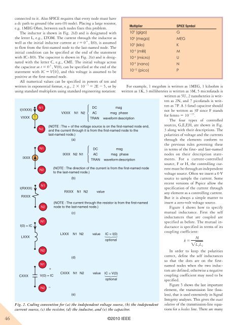
The inductor is shown in Fig. 2(d) and is designated with<br />
the letter L, e.g., LTOM. The current through the inductor as<br />
well as the initial inductor current at t 5 0 1 , I(0), is assumed<br />
to flow from the first-named node to the last-named node. The<br />
initial condition can be specified at the end of the statement<br />
with IC=I(0). The capacitor is shown in Fig. 2(e) and is designated<br />
with the letter C, e.g., CME. The initial voltage across<br />
the capacitor at t 5 0 1 , V(0), can be specified at the end of the<br />
statement with IC 5 V102, and this voltage is assumed to be<br />
positive at the first-named node.<br />
All numerical values can be specified in powers of ten and<br />
written in exponential format, e.g., 2 3 10 25 5 2E 2 5, or by<br />
<strong>using</strong> standard multipliers <strong>using</strong> standard engineering notation:<br />
I(VXXX)<br />
N1<br />
VXXX<br />
+<br />
–<br />
IXXX<br />
I(RXXX)<br />
RXXX<br />
I(0) = IC<br />
LXXX<br />
CXXX<br />
N2<br />
N1<br />
N2<br />
N1<br />
N2<br />
N1<br />
N2<br />
N1<br />
V(0) = IC<br />
N2<br />
(NOTE : The + of the voltage source is on the first-named node end,<br />
and the current through it is from the first-named node to the<br />
last-named node.)<br />
(a)<br />
+<br />
–<br />
VXXX N1 N2 µ<br />
IXXX<br />
LXXX<br />
N2 N1<br />
value<br />
IC = I(0)<br />
optional<br />
46 ©2010 <strong>IEEE</strong><br />
N1<br />
N2<br />
µ<br />
DC<br />
AC<br />
TRAN<br />
waveform description<br />
µ<br />
mag<br />
mag<br />
For example, 1 megohm is written as 1MEG, 1 kiloohm is<br />
written as 1K, 3 millihenries is written as 3M, 5 microfarads is<br />
written as 5U, 2 nanohenries is written<br />
as 2N, and 7 picofarads is writ-<br />
phase<br />
(NOTE : The direction of the current is from the first-named node<br />
to the last-named node.)<br />
RXXX<br />
(b)<br />
N1<br />
N2<br />
value<br />
(NOTE : The current through the resistor is from the first-named<br />
node to the last-named node.)<br />
CXXX<br />
(c)<br />
(d)<br />
N1<br />
(e)<br />
N2<br />
DC<br />
AC<br />
TRAN<br />
value<br />
mag<br />
mag<br />
phase<br />
waveform description<br />
IC = V(0)<br />
µ<br />
optional<br />
Fig. 2. Coding convention for (a) the independent voltage source, (b) the independent<br />
current source, (c) the resistor, (d) the inductor, and (e) the capacitor.<br />
Multiplier <strong>SPICE</strong> Symbol<br />
10 9 (giga) G<br />
10 6 (mega) MEG<br />
10 3 (kilo) K<br />
10 –3 (milli) M<br />
10 –6 (micro) U<br />
10 –9 (nano) N<br />
10 –12 (pico) P<br />
ten as 7P. A 3 farad capacitor should<br />
not be written as 3F since F stands<br />
for femto 5 10 215 .<br />
The four types of controlled<br />
sources, G,E,F,H, are shown in Fig.<br />
3 along with their descriptions. The<br />
polarities of voltage and the currents<br />
through the elements conform to<br />
the previous rules governing these<br />
in terms of the first- and last-named<br />
nodes on their description statements.<br />
For a current-controlled<br />
source, F or H, the controlling current<br />
must be through an independent<br />
voltage source. Often we insert a 0 V<br />
source to sample the current. Some<br />
recent versions of Pspice allow the<br />
specification of the current through<br />
any element as a controlling current.<br />
But it is always a simple matter to<br />
insert a zero-volt voltage source.<br />
Figure 4 shows how to specify<br />
mutual inductance. First the self<br />
inductances that are coupled are<br />
specified as before. The mutual inductance<br />
is specified in terms of its<br />
coupling coefficient:<br />
k 5 M<br />
"L 1L 2<br />
In order to keep the polarities<br />
correct, define the self inductances<br />
so that the dots are on the firstnamed<br />
nodes when the two inductors<br />
are defined; otherwise a negative<br />
coupling coefficient may need to be<br />
specified.<br />
Figure 5 shows the last important<br />
element, the transmission line (lossless),<br />
that is used extensively in <strong>Signal</strong><br />
<strong>Integrity</strong> analyses. This gives the exact<br />
solution of the transmission-line equations<br />
for a lossless line. There are many


