

Tutorial: EMC & Signal Integrity using SPICE, page 44 - IEEE EMC ...
Tutorial: EMC & Signal Integrity using SPICE, page 44 - IEEE EMC ...
Tutorial: EMC & Signal Integrity using SPICE, page 44 - IEEE EMC ...

Create successful ePaper yourself
Turn your PDF publications into a flip-book with our unique Google optimized e-Paper software.
case, for R 5 20 m and g 5 0.50 m, SE 5 22 dB.<br />
For those specific indoor areas which are protected by a second<br />
grid, the additional attenuation has been evaluated at 9 dB.<br />
Vii. Scale Model Validation<br />
The validation tests via a downscale model were an interesting<br />
part of the study. The design of this mock-up has been a tradeoff<br />
between multiple constraints:<br />
•<br />
•<br />
•<br />
•<br />
•<br />
Table 3. summary of aTTenuaTions and reCeived<br />
field, 3m inside, for indireCT impaCT aT 20m.<br />
Basic received H field at 20 m 1 3 m (Eq.1) :<br />
H 0 5 I 0 / 2p x 23 5 0.007. I 0<br />
Attenuation of 0.50 3 0.50 grid alone (Eq.2) :<br />
22 dB (that is a 0.075 transmission factor )<br />
Waveform #1 Waveform #2<br />
H 0 at 20 m 1 3 m 1380 A/m 350 A/m<br />
Atten. of 1st grid<br />
(Eq.2) 0.075(22 dB) 0.075<br />
Atten. of 2nd grid : 0.35 (9 dB) 0.35<br />
Cumulated<br />
attenuation. 0.027 (32 dB) 0.027<br />
Residual Field HX: 37 a/m 9.5 a/m<br />
the mock-up had to be lightweight, easy to carry and install,<br />
because it had to be moved to several places for quick<br />
demonstrations to facilities managers.<br />
the scale factor had to match the risetime of the kiloVolt pulse<br />
generator used for current injection, but also match with the<br />
grid size of the mock-up.<br />
the mock-up had to offer an optional, smaller mesh-grid box<br />
inside the main cage, with an easy mounting fixture<br />
calibrated H-field and current sensors had to be small enough<br />
to fit inside both boxes, without interfering significantly with<br />
the natural field-distribution<br />
the whole measuremen gear, coaxial cables, connectors and<br />
memory oscilloscope had to be enough decoupled/shielded,<br />
preventing the measurements from being corrupted by the<br />
strong kV and tens of Amperes pulse injection.<br />
A. Description<br />
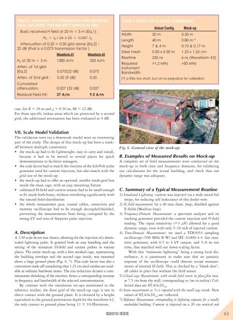
A 1/40 scale factor was chosen, allowing for the injection of a downscaled<br />
lightning pulse. It granted both an easy handling and the<br />
setting of the miniature H-field and current probes in various<br />
places. The entire mock-up, with a first meshed cage, representing<br />
the building envelope and the second cage inside, was mounted<br />
above a large ground plane (Fig. 6, 7). This scale factor was also a<br />
convenient trade-off considering that 1.25 cm steel meshes are available<br />
at ordinary hardware stores. The size reduction dictates a commensurate<br />
shrinking of the risetime, hence a corresponding increase<br />
in frequency and bandwidth of the selected instrumentation.<br />
By contrast with the simulation set-ups mentioned in the<br />
reference studies, the floor grid of the mock-up cage is not in<br />
direct contact with the ground plane. It is elevated by a height<br />
equivalent to the ground penetration depth for the waveform #2,<br />
the only contact to ground plane being 12 3 10-Vresistors.<br />
©2010 <strong>IEEE</strong><br />
Table 4. moCk-up sCaling parameTers.<br />
Actual Config. Mock-up<br />
Width 20 m 0.50 m<br />
Length 40 m 0.80 m *<br />
Height 7 & 4 m 0.10 & 0.17 m<br />
Steel mesh 0.50 x 0.50 m 1.25 x 1.25 cm<br />
Risetime 250 ns 6 ns (Waveform #2)<br />
Required<br />
instrument<br />
Bandwidth<br />
>1.2 MHz >50 MHz<br />
(*) a little too short, but at no prejudice for validation<br />
Fig. 6. General view of the mock-up.<br />
B. Examples of Measured Results on Mock-up<br />
A complete set of field measurements were conducted on the<br />
mock-up in both time and frequency domains, for validating<br />
our calculations for the actual building, and check that our<br />
dynamic range was adequate.<br />
C. Summary of a Typical Measurement Routine<br />
1) Simulated Lightning: current was injected via a wide metal foil<br />
stripe, for reducing self inductance of this feeder wire.<br />
2) H field measurement: by a 40 mm diam. loop, shielded against<br />
E-fields (Moebius loop).<br />
3) Frequency-Domain Measurements: a spectrum analyser and its<br />
tracking generator provided the current injection and H field<br />
reading. The input sensitivity (


