

Tutorial: EMC & Signal Integrity using SPICE, page 44 - IEEE EMC ...
Tutorial: EMC & Signal Integrity using SPICE, page 44 - IEEE EMC ...
Tutorial: EMC & Signal Integrity using SPICE, page 44 - IEEE EMC ...

You also want an ePaper? Increase the reach of your titles
YUMPU automatically turns print PDFs into web optimized ePapers that Google loves.
Lightning-Generated Fields in<br />
Reinforced concrete Buildings<br />
Michel Mardiguian <strong>EMC</strong> Consultant, 2, Allée des Chataigniers<br />
78470 St Rémy les Chevreuse, France E-mail: m.mardiguian@orange.fr<br />
Abstract— This contribution presents a study, model and validation<br />
of the amplitudes of the residual fields inside a one-story building<br />
for different locations of lightning impacts. The special case where<br />
a second gridded structure exist inside the main building, forming<br />
a box-in-the-box configuration, is analyzed. We show also that<br />
formulas for magnetic field attenuation found in the relevant IEC<br />
documents are questionable, under certain conditions.<br />
i. introduction<br />
When a lightning strikes a building (direct hit) or a nearby<br />
point, besides the abrupt change in local ground potential, an<br />
intense electromagnetic field radiates from the lightning channel.<br />
Even with a gridded concrete building like the one investigated<br />
here, the residual field inside can still induce transient<br />
voltages which can damage electronic equipment and electrical<br />
hardware. Although a large amount of data and standard documentation<br />
are available regarding conducted and radiated effects<br />
of lightning on steel-reinforced facilities, certain areas are not<br />
fully covered, like the case where a second gridded structure<br />
exists inside the main building, forming a box-in-the-box configuration.<br />
Generally, with ordinary facilities, a risk analysis is<br />
conducted, to balance the cost of the lightning protection measures<br />
versus the financial loss incurred if there was no protection.<br />
However in a case like ours, the cost of the systems installed in<br />
the building was such that a maximum risk coverage was<br />
requested. That is, we did not have to gamble about the fact that<br />
a worst lightning current might happen, but to take for certain<br />
that it will happen. The present article is a shortened version of<br />
our study, stripped of many calculation details and foc<strong>using</strong><br />
mostly on the validation experiments carried on a representative<br />
1/40 scale model. More details are available from the Author.<br />
A. Structure Under Study<br />
The building can be assimilated to a 40 m 3 20 m 3 4 m<br />
cubicle with reinforced concrete walls, ceiling and floor slab.<br />
Electromagnetic shielding is made by 0.50 m grid with 20 mm<br />
diameter steel bars, welded at intersections. The floor slab is<br />
resting on a soil of unknown conductivity, but goose leg-type<br />
earthing electrodes are evenly spread at 8m intervals on the<br />
perimeter, each one with an earthing resistance # 10 V.<br />
Inside the building, at a 1.8m distance from the overall grid,<br />
few specific zones are protected by a second barrier with similar<br />
0.50 3 0.50 grid, welded to the concrete floor armature. The access<br />
doors are metallic, with bonding contacts at regular intervals.<br />
B. Lightning Parameters<br />
IEC norms provide a precise formula for the time domain waveform<br />
I1t2of the stroke current, which is different from the usual<br />
double exponential, avoiding a singularity at the curve start-<br />
58 ©2010 <strong>IEEE</strong><br />
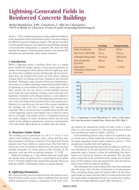
Table 1. waveforms for The Two<br />
(severiTy Class one) lighTning pulses.<br />
First Stroke Subsequent Stroke<br />
Peak Amplitude 200 kA 50 kA<br />
Rise time (10%–90%) 10 µs 0.25 µs<br />
Average rising slope 20 kA/µs 200 kA/µs<br />
Mid-amplitude<br />
Duration<br />
Equivalent<br />
Frequency (Spectral<br />
domain)<br />
360 µs 100 µs<br />
30 kHz 1.2 MHz<br />
300<br />
250<br />
200<br />
150<br />
100<br />
50<br />
0<br />
–50<br />
0 5 10 15 20 25<br />
µs<br />
30 35 40 45 50<br />
Fig. 1. Lightning Current Waveforms #1 and 2, with respective<br />
time derivatives (dotted lines, kA/µs) per IEC (Ref.1)<br />
up, whereas the exponential would rise from a null to a finite<br />
slope in a zero time interval [1]. The essential features of these<br />
two waveforms are shown on Table 1 and Fig. 1.<br />
In the modelling analysis, these currents are regarded as ideal<br />
current sources, whose amplitude and slope are not altered by<br />
the target impedance (tower, down conductor, grid etc..). This<br />
assumption is totally valid with lightning.<br />
The dI/dt rising slope has practically no influence on the current<br />
distribution in the grid elements of the target. This is an<br />
important aspect, because it allow for establishing this distribution<br />
once and for all, whatever the waveform. Yet, the slope<br />
plays a major role in the calculation of the voltage rise of various<br />
parts of the building versus the ground level, and the field-tocable<br />
induced effects inside the building.<br />
The subsequent fast stroke exhibits four times less amplitude<br />
than the initial “slow”one, but its derivative is 10 times greater.<br />
Thus, everything being equal, the induced effects by the subsequent<br />
stroke in a same structure will be 10 times worse than with<br />
the initial stroke, eventhough this latter is ca<strong>using</strong> more conduction<br />
effects (voltage differences, Joule effect heating etc ..).


