

Tutorial: EMC & Signal Integrity using SPICE, page 44 - IEEE EMC ...
Tutorial: EMC & Signal Integrity using SPICE, page 44 - IEEE EMC ...
Tutorial: EMC & Signal Integrity using SPICE, page 44 - IEEE EMC ...

Create successful ePaper yourself
Turn your PDF publications into a flip-book with our unique Google optimized e-Paper software.
ii. Summary Of Modeling Approach<br />
A. Parameters, constraints and<br />
simplifications used<br />
Each rise time defines an “equivalent frequency”, allowing<br />
for quick results when calculations are easier to carry out in<br />
frequency than time domain. For a first order coupling mechanism,<br />
this equivalent frequency is taken as:<br />
F equ. 5 0.32/tm where t m is the 10%–90% risetime. This<br />
will be used to define the penetration depth in the ground, skin<br />
effect in the steel rebars, Near-to-Far Field transition distance etc ...<br />
Each bar of the outer and inner grids are modeled as cylinders<br />
with length l 5 0.50 m, and diam. d 5 20 mm. Each<br />
wire is modelled by an impedance<br />
Z 5 R ac 1 jvL<br />
with R ac : resistance of the steel bar at frequency F equ., accounting<br />
for the skin effect and the decrease in relative permeability<br />
µr above hundred kHz<br />
R ac 5 R dc / 1d/4d2<br />
R dc (up to the beginning of skin depth regime)=<br />
rl/s 5 0.16 mV<br />
r : steel resistivity < 10 mV.cm<br />
d : skin depth 5 0.3 /UfkHzfor steel up to hundreds of kHz<br />
L : self-inductance of one<br />
0.50 m bar 5 0.2 Ln14l/d2.0.50 m 5 0.46 mH.<br />
Several buildings were foreseen in different locations, with<br />
ground resistivities varying from 30 V.m to 1000 V.m. However,<br />
since the earthing electrodes resistances were defined as a<br />
fixed parameter and considered as the only dependable link to<br />
the ground, essential calculations can be made without the<br />
need of ground resistivity.<br />
All parameters used as modeling inputs are summarized in<br />
Table 2 and allow to validate some simplifications.<br />
B. Conclusion About Parameters<br />
• Impedance of grid bars is dominated by self-inductance, even<br />
for the slow-rising front<br />
• Inductance & Resistance of grid bars have no influence on the<br />
injected current amplitude and waveform, which are imposed by<br />
the quasi-perfect current source of the lightning phenomena.<br />
• They have no effect either on the spread of currents in the<br />
grid members, since the current source and the 10 V earth<br />
rods have impedances much greater than those of the grid<br />
cells.<br />
• The penetration depth in ground gives the distance of the<br />
image plane (virtual ground plane) where one can consider<br />
that the reflection of incident field will take place ( Ref.6).<br />
• All radiated couplings take place in the near-field, or quasistatic<br />
domain.<br />
• the grid cell size (0.50 3 0.50 m) is such that concrete capacity<br />
and resistivity, that are shunting the steel bar impedance,<br />
can be neglected in calculations. We are also far below the self<br />
resonance of a concrete-buried cell (100 MHz).<br />
• the cell dimension makes the bar-to-bar mutual inductance<br />
negligible. Two parallel bars can be seen as independent<br />
inductances, the current in one having no influence<br />
on the other.<br />
©2010 <strong>IEEE</strong><br />
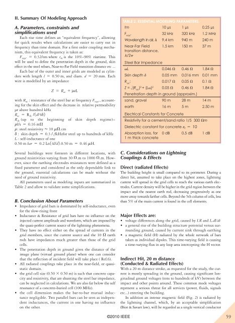
Table 2. essenTial modeling parameTers.<br />
tm 10 µs 1 µs 0.25 µs<br />
F equ . 32 kHz 320 kHz 1.2 MHz<br />
Wavelength in air, l 9.4 km 940 m 240 m<br />
Near-Far Field<br />
transition distance,<br />
l/2p<br />
1.5 km 150 m 37 m<br />
Steel Bar Impedance<br />
vL 0.046 V 0.46 V 1.84 V<br />
Skin depth d 0.05 mm 0.016 mm 0.01 mm<br />
R : ac 0.017 V 0.05 V 0.1 V<br />
Z = !(R ) ac 2 + (Lv) 2 0.05 V 0.46 V 1.84 V<br />
Penetration depth in ground (approxim.)<br />
sand, gravel 90 m 28 m 14 m<br />
earth 16 m 5 m 2.50 m<br />
Electrical Constants for Concrete<br />
Resistivity for a cement/sand ratio 1/5 300 Vm<br />
Dielectric constant for concrete er 5 10<br />
Absorption loss, for<br />
1 m thick concrete<br />
0 dB 0.5 dB 1 dB<br />
C. Considerations on Lightning<br />
Couplings & Effects<br />
Direct (radiated effects)<br />
The building height is small compared to its perimeter. During a<br />
direct hit, assumed to take place on the highest zones, lightning<br />
current will spread in the grid cells to reach the various earth electrodes.<br />
Current density will be higher in the grid region between the<br />
impact and the nearest earth rod, decreasing progressively as one<br />
move away towards farther cells. Beyond the 5th column of cells, less<br />
than 5% of the main current is found in the cell elements.<br />
Major effects are:<br />
• voltage differences along the grid, caused by I.R and L.dI/dt<br />
• a general rise of the building structure potential versus surrounding<br />
ground, caused by current sink through earthing<br />
• a magnetic field (H) radiated by the whole network of bars<br />
taken as individual dipoles. This time-varying field is ca<strong>using</strong><br />
a time-varying flux in any loop area intercepting the H vector.<br />
indirect Hit, 20 m distance<br />
(conducted & Radiated effects)<br />
With a 20 m distance stroke, as requested for the study, the current<br />
is mostly spreading in the ground, ca<strong>using</strong> significant longitudinal<br />
ground voltages (tens to hundreds of kV) between the<br />
impact and other points around. These common mode voltages<br />
represent a serious threat for all services (power, fluids, signals<br />
etc...) entering the building.<br />
In addition an intense magnetic field (Fig. 2) is radiated by<br />
the lightning channel, which, by an acceptable simplification<br />
(Biot & Savart law), will be regarded as a single vertical conductor<br />
59


