UNIVERSIT . . AT BONN Physikalisches Institut - Prof. Dr. Norbert ...
UNIVERSIT . . AT BONN Physikalisches Institut - Prof. Dr. Norbert ...
UNIVERSIT . . AT BONN Physikalisches Institut - Prof. Dr. Norbert ...

You also want an ePaper? Increase the reach of your titles
YUMPU automatically turns print PDFs into web optimized ePapers that Google loves.
118 8. X-ray images<br />
By placing a different section of the PMMA wedge next to the Al sheet, the contrast in<br />
the phantom can be adjusted. Note that because of the similar absorption properties of<br />
Al and PMMA to human tissue, this selection of the absorber materials simulates a thin<br />
bone (Al) placed next to a thicker muscle (PMMA).<br />
First of all the number of photons per second, the integrator current and the absorbed<br />
spectrum behind 1 mm Al and 1 mm to 10 mm PMMA were simulated. The impinging<br />
X-ray spectrum in the simulation was chosen such that it corresponds to the spectrum of<br />
the Hamamatsu X-ray tube at 90 kVp, including the additional low energy filter consisting<br />
of 1 mm of Al. From these simulation data, the image contrast C can be calculated<br />
according to the following definition:<br />
C = AP MMA − AAl<br />
AP MMA + AAl<br />
(8.1)<br />
The variables AP MMA and AAl represent the signal amplitudes behind the PMMA wedge<br />
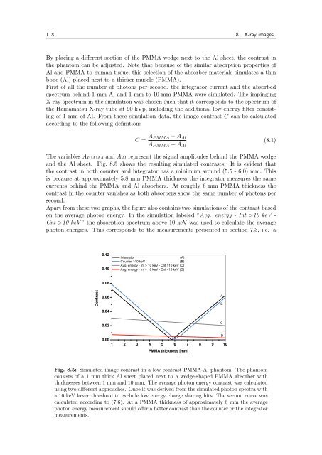
and the Al sheet. Fig. 8.5 shows the resulting simulated contrasts. It is evident that<br />
the contrast in both counter and integrator has a minimum around (5.5 - 6.0) mm. This<br />
is because at approximately 5.8 mm PMMA thickness the integrator measures the same<br />
currents behind the PMMA and Al absorbers. At roughly 6 mm PMMA thickness the<br />
contrast in the counter vanishes as both absorbers show the same number of photons per<br />
second.<br />
Apart from these two graphs, the figure also contains two simulations of the contrast based<br />
on the average photon energy. In the simulation labeled ”Avg. energy - Int >10 keV -<br />
Cnt >10 keV ” the absorption spectrum above 10 keV was used to calculate the average<br />
photon energies. This corresponds to the measurements presented in section 7.3, i.e. a<br />
C o n tr a s t<br />
0 .1 2<br />
0 .1 0<br />
0 .0 8<br />
0 .0 6<br />
0 .0 4<br />
0 .0 2<br />
0 .0 0<br />
In te g ra to r (A )<br />
C o u n te r > 1 0 k e V (B )<br />
A v g . e n e rg y - In t > 1 0 k e V - C n t > 1 0 k e V (C )<br />
A v g . e n e rg y - In t > 0 k e V - C n t > 1 0 k e V (D )<br />
1 2 3 4 5 6 7 8 9 1 0<br />
P M M A th ic k n e s s [m m ]<br />
Fig. 8.5: Simulated image contrast in a low contrast PMMA-Al phantom. The phantom<br />
consists of a 1 mm thick Al sheet placed next to a wedge-shaped PMMA absorber with<br />
thicknesses between 1 mm and 10 mm. The average photon energy contrast was calculated<br />
using two different approaches. Once it was derived from the simulated photon spectra with<br />
a 10 keV lower threshold to exclude low energy charge sharing hits. The second curve was<br />
calculated according to (7.6). At a PMMA thickness of approximately 6 mm the average<br />
photon energy measurement should offer a better contrast than the counter or the integrator<br />
measurements.<br />
A<br />
B<br />
C<br />
D