UNIVERSIT . . AT BONN Physikalisches Institut - Prof. Dr. Norbert ...
UNIVERSIT . . AT BONN Physikalisches Institut - Prof. Dr. Norbert ...
UNIVERSIT . . AT BONN Physikalisches Institut - Prof. Dr. Norbert ...

Create successful ePaper yourself
Turn your PDF publications into a flip-book with our unique Google optimized e-Paper software.
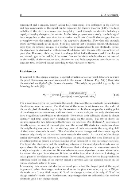
14 2. X-ray imaging<br />
component and a smaller, longer lasting hole component. The difference in the electron<br />
and hole components of the signal can be explained by Ramo’s theorem (2.11). The high<br />
mobility of the electrons causes them to quickly travel through the detector inducing a<br />
rapidly changing charge at the anode. As the holes progress more slowly, the hole signal<br />
lasts longer but at the same time has a smaller amplitude. Overall, the charge collection<br />
is complete once the carriers arrive at the respective electrodes. Note that this example<br />
treats only the signals at the anode. Still, it is evident that a negative charge, which moves<br />
away from the cathode, is equal to a positive charge moving closer to said electrode. Hence,<br />
the signal can be observed at both sides of the detector with the sole difference of inverted<br />
polarities. However, this is only true if no charge is lost inside the sensor and if the charges<br />
are created right in the middle of the sensor. In case the electron-hole pairs are not created<br />
in the middle of the sensor volume, the electron and hole components contribute to the<br />
constant total collected charge according to their distance of travel.<br />
Pixel detector<br />
In contrast to this simple example, a special situation arises for pixel detectors in which<br />
the pixel dimensions are small compared to the sensor thickness. Fig. 2.8(b) illustrates<br />
the so-called small-pixel effect in one dimension. The weighting potential is given by the<br />
following formula [29]:<br />
Φw = 1<br />
π arctan<br />
�<br />
sin(πy)sinh(π a<br />
2 )<br />
cosh(πx) − cos(πy)cosh(π a<br />
2 )<br />
�<br />
(2.14)<br />
The x coordinate gives the position in the anode plane and the y coordinate parameterizes<br />
the distance from the anode. The thickness of the sensor is set to one and the width of<br />
the anode pixel electrodes is given by the constant a. In this example the starting point<br />
of the charge carrier movement is chosen close to the cathode, so that only the electrons<br />
have a significant contribution to the signals. Holes reach their collecting electrode almost<br />
instantly and thus induce only a negligible signal on the anode. Fig. 2.8(b) shows the<br />
induced signals for two different paths through the detector. One electron (A) is generated<br />
directly above the central read-out pixel and the second (B) starts its translation above<br />
the neighboring electrode. At the starting point of both movements the weighting field<br />
of the central electrode is weak. Therefore the induced charge and the current signals<br />
increase only slowly as the carriers move towards the anode. At the end of the charge<br />
carrier movement, when electron A approaches the central pixel, the steep increase in the<br />
weighting potential causes a strong coupling of the movement to this particular electrode.<br />
The figure also illustrates that the weighting potential of the central pixel extends into the<br />
space above the neighboring pixels. This means that a charge carrier movement towards<br />
a neighboring electrode (electron B) also induces a current signal on the central electrode.<br />
As shown, the signal from electron B does not differ from that of electron A during the<br />
initial phase of the charge carrier movement. Nevertheless, once electron B approaches its<br />
collecting pixel the sign of the current signal is inverted and the induced charge on the<br />
central electrode returns to zero.<br />
In summary this means that due to the small pixel effect the largest part of the signal<br />
is generated when the charge carriers are close to the pixel electrodes, e.g. at a 250 µm<br />
electrode on a 3 mm thick sensor 90 % of the charge is collected in only 40 % of the<br />
charge carrier’s transit time. Furthermore, only charges that are collected at the read-out<br />
electrode yield a net charge signal.