UNIVERSIT . . AT BONN Physikalisches Institut - Prof. Dr. Norbert ...
UNIVERSIT . . AT BONN Physikalisches Institut - Prof. Dr. Norbert ...
UNIVERSIT . . AT BONN Physikalisches Institut - Prof. Dr. Norbert ...

You also want an ePaper? Increase the reach of your titles
YUMPU automatically turns print PDFs into web optimized ePapers that Google loves.
3.3. CIX 0.2 pixel cell concept 33<br />
and thus injects a configurable amount of charge into the Int node. The size of the<br />
charge packet is determined by the potential difference between VP umpHi and VP umpLo.<br />
The VP umpMean connection guarantees that the action of the switches themselves does not<br />
inject additional charges. Apart from the capacitive charge pump, the system also features<br />
a switched constant current source. This circuit discharges CInt by enabling the IP ump<br />
current source for half a CKInt clock cycle. The size of the individual QP ump packets is<br />
controlled by the current source’s DAC setting. More details on the charge pumps can be<br />
found in [1].<br />
3.3.3 Feedback<br />
The feedback circuit of CIX 0.2 is the heart of the simultaneously counting and integrating<br />
concept. Its task is to discharge the counter preamplifier and at the same time to<br />
reproduce the input current for the integrator. These at first glimpse conflicting requirements<br />
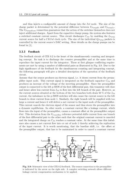
are met by using a number of differential pairs as illustrated in Fig. 3.9. Due to the<br />
high significance of the feedback for the simultaneous counting and integrating concept,<br />
the following paragraph will give a detailed description of the operation of the feedback<br />
circuit.<br />
Assume that the sensor produces an electron signal, i.e. it draws current from the preamplifier<br />
input node. This current signal is integrated on the feedback capacitor CF b and<br />
produces an increase of the voltage of the inverting preamplifier. Since the preamplifier<br />
output is connected to the left p-MOS of the first differential pair, this transistor will close<br />
and hence allow less current from IF b to flow into the left branch of the pair. However, as<br />
the current sources situated at the bottom of the two branches both drain 50 % of the IF b<br />
current, the imbalance in the p-MOS switches will also cause the current source in the left<br />
branch to draw current from node 1. Similarly, the right branch will be supplied with too<br />
large a current and hence it will deliver a net current to the input node of the preamplifier.<br />
This current cancels the electron signal of the sensor and thus steers the preamplifier into<br />
a dynamic equilibrium. In other words, a constant current like a leakage current, which<br />
flows into the input of the preamplifier, causes a constant offset at the preamplifier output<br />
Out. This deviation from the VCountRef reference potential shifts current from one branch<br />
of the first differential pair to the other such that the original constant current is canceled<br />
and the integrated charge on CF b reaches a constant value. At the same time this imbalance<br />
also causes a net current flow into or out of node 1 thereby achieving the replication<br />
of the input current. It is worth mentioning, that the baseline shift, i.e. the offset at<br />
the preamplifier output, that has to be maintained in order to cancel a constant current<br />
B<br />
VCountRef<br />
D<br />
ILeakComp<br />
2<br />
2 nd<br />
Ca<br />
A<br />
C<br />
E E<br />
E<br />
1 st<br />
1<br />
IFb<br />
VCount-<br />
Baseline<br />
In<br />
sensor<br />
input node<br />
VCountRef<br />
CFb<br />
Out<br />
bypass<br />
transitor<br />
integrator<br />
Fig. 3.9: Schematic view of the CIX 0.2 feedback. The sensor connection to the preamplifier<br />
is indicated by the arrow on the right side. A complex switching network allows different<br />
leakage current compensation mechanism to be applied.