UNIVERSIT . . AT BONN Physikalisches Institut - Prof. Dr. Norbert ...
UNIVERSIT . . AT BONN Physikalisches Institut - Prof. Dr. Norbert ...
UNIVERSIT . . AT BONN Physikalisches Institut - Prof. Dr. Norbert ...

Create successful ePaper yourself
Turn your PDF publications into a flip-book with our unique Google optimized e-Paper software.
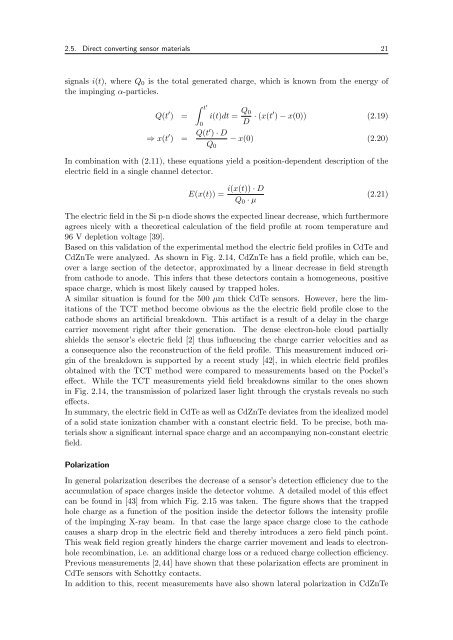
2.5. Direct converting sensor materials 21<br />
signals i(t), where Q0 is the total generated charge, which is known from the energy of<br />
the impinging α-particles.<br />
� t ′<br />
Q(t ′ ) =<br />
0<br />
i(t)dt = Q0<br />
D · (x(t′ ) − x(0)) (2.19)<br />
⇒ x(t ′ ) = Q(t′ ) · D<br />
− x(0) (2.20)<br />
Q0<br />
In combination with (2.11), these equations yield a position-dependent description of the<br />
electric field in a single channel detector.<br />
E(x(t)) =<br />
i(x(t)) · D<br />
Q0 · µ<br />
(2.21)<br />
The electric field in the Si p-n diode shows the expected linear decrease, which furthermore<br />
agrees nicely with a theoretical calculation of the field profile at room temperature and<br />
96 V depletion voltage [39].<br />
Based on this validation of the experimental method the electric field profiles in CdTe and<br />
CdZnTe were analyzed. As shown in Fig. 2.14, CdZnTe has a field profile, which can be,<br />
over a large section of the detector, approximated by a linear decrease in field strength<br />
from cathode to anode. This infers that these detectors contain a homogeneous, positive<br />
space charge, which is most likely caused by trapped holes.<br />
A similar situation is found for the 500 µm thick CdTe sensors. However, here the limitations<br />
of the TCT method become obvious as the the electric field profile close to the<br />
cathode shows an artificial breakdown. This artifact is a result of a delay in the charge<br />
carrier movement right after their generation. The dense electron-hole cloud partially<br />
shields the sensor’s electric field [2] thus influencing the charge carrier velocities and as<br />
a consequence also the reconstruction of the field profile. This measurement induced origin<br />
of the breakdown is supported by a recent study [42], in which electric field profiles<br />
obtained with the TCT method were compared to measurements based on the Pockel’s<br />
effect. While the TCT measurements yield field breakdowns similar to the ones shown<br />
in Fig. 2.14, the transmission of polarized laser light through the crystals reveals no such<br />
effects.<br />
In summary, the electric field in CdTe as well as CdZnTe deviates from the idealized model<br />
of a solid state ionization chamber with a constant electric field. To be precise, both materials<br />
show a significant internal space charge and an accompanying non-constant electric<br />
field.<br />
Polarization<br />
In general polarization describes the decrease of a sensor’s detection efficiency due to the<br />
accumulation of space charges inside the detector volume. A detailed model of this effect<br />
can be found in [43] from which Fig. 2.15 was taken. The figure shows that the trapped<br />
hole charge as a function of the position inside the detector follows the intensity profile<br />
of the impinging X-ray beam. In that case the large space charge close to the cathode<br />
causes a sharp drop in the electric field and thereby introduces a zero field pinch point.<br />
This weak field region greatly hinders the charge carrier movement and leads to electronhole<br />
recombination, i.e. an additional charge loss or a reduced charge collection efficiency.<br />
Previous measurements [2,44] have shown that these polarization effects are prominent in<br />
CdTe sensors with Schottky contacts.<br />
In addition to this, recent measurements have also shown lateral polarization in CdZnTe