Datascope Passport - Mindray
Datascope Passport - Mindray
Datascope Passport - Mindray
You also want an ePaper? Increase the reach of your titles
YUMPU automatically turns print PDFs into web optimized ePapers that Google loves.
Theory of Operation Nellcor/Interface Board<br />
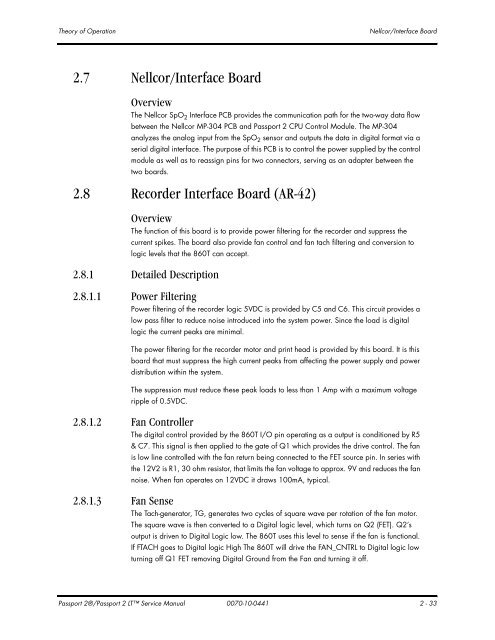
2.7 Nellcor/Interface Board<br />
Overview<br />
The Nellcor SpO2 Interface PCB provides the communication path for the two-way data flow<br />
between the Nellcor MP-304 PCB and <strong>Passport</strong> 2 CPU Control Module. The MP-304<br />
analyzes the analog input from the SpO2 sensor and outputs the data in digital format via a<br />
serial digital interface. The purpose of this PCB is to control the power supplied by the control<br />
module as well as to reassign pins for two connectors, serving as an adapter between the<br />
two boards.<br />
2.8 Recorder Interface Board (AR-42)<br />
Overview<br />
The function of this board is to provide power filtering for the recorder and suppress the<br />
current spikes. The board also provide fan control and fan tach filtering and conversion to<br />
logic levels that the 860T can accept.<br />
2.8.1 Detailed Description<br />
2.8.1.1 Power Filtering<br />
Power filtering of the recorder logic 5VDC is provided by C5 and C6. This circuit provides a<br />
low pass filter to reduce noise introduced into the system power. Since the load is digital<br />
logic the current peaks are minimal.<br />
The power filtering for the recorder motor and print head is provided by this board. It is this<br />
board that must suppress the high current peaks from affecting the power supply and power<br />
distribution within the system.<br />
The suppression must reduce these peak loads to less than 1 Amp with a maximum voltage<br />
ripple of 0.5VDC.<br />
2.8.1.2 Fan Controller<br />
2.8.1.3 Fan Sense<br />
The digital control provided by the 860T I/O pin operating as a output is conditioned by R5<br />
& C7. This signal is then applied to the gate of Q1 which provides the drive control. The fan<br />
is low line controlled with the fan return being connected to the FET source pin. In series with<br />
the 12V2 is R1, 30 ohm resistor, that limits the fan voltage to approx. 9V and reduces the fan<br />
noise. When fan operates on 12VDC it draws 100mA, typical.<br />
The Tach-generator, TG, generates two cycles of square wave per rotation of the fan motor.<br />
The square wave is then converted to a Digital logic level, which turns on Q2 (FET). Q2’s<br />
output is driven to Digital Logic low. The 860T uses this level to sense if the fan is functional.<br />
If FTACH goes to Digital logic High The 860T will drive the FAN_CNTRL to Digital logic low<br />
turning off Q1 FET removing Digital Ground from the Fan and turning it off.<br />
<strong>Passport</strong> 2®/<strong>Passport</strong> 2 LT Service Manual 0070-10-0441 2 - 33


