6 - MV Agusta
6 - MV Agusta
6 - MV Agusta

Create successful ePaper yourself
Turn your PDF publications into a flip-book with our unique Google optimized e-Paper software.
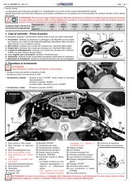
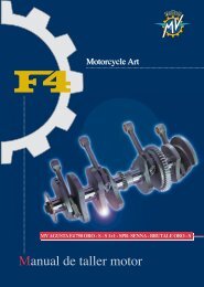
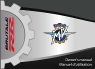
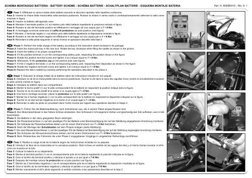
SCHEMA MONTAGGIO BATTERIA - BATTERY SCHEME - SCHÉMA BATTERIE - SCHALTPLAN BATTERIE - ESQUEMA MONTAJE BATERIA Part. N. 8000B5419 - Rev. N. 1IT Fase 1: Effettuare la carica iniziale della batteria secondo le istruzioni riportate nella rispettiva confezione.Fase 2: Inserire la chiave della motocicletta nella serratura posteriore. Ruotare la chiave in senso orario e contemporaneamente sollevare la sella comemostrato in figura.Fase 3: Inserire la batteria nell’apposito vano.Fase 4: Montare il terminale positivo (+) sul relativo polo della batteria rispettando la posizione indicata in figura.Fase 5: Ruotare la vite del terminale positivo ed effettuarne il serraggio ad una coppia pari a 7 ÷ 8 Nm.Fase 6: A montaggio avvenuto sistemare la cuffia di protezione sul polo positivo (vedi figura).Fase 7: Montare i 2 terminali negativi (-) sul relativo polo della batteria rispettando la disposizione mostrata in figura.Fase 8: Ruotare la vite dei terminali negativi ed effettuarne il serraggio ad una coppia pari a 7 ÷ 8 Nm.Fase 9: Rimontare la sella pilota seguendo in senso inverso le operazioni descritte nella fase 2.1. 2.GB Phase 1: Perform the initial charge of the battery according to the instruction sheet enclosed in its package.Phase 2: Insert the motorcycle key in the rear lock. Rotate the key clockwise while lifting the saddle as shown in the picture.Phase 3: Insert the battery in its proper compartment.Phase 4: Fit the positive terminal (+) on the corresponding battery pole, respecting the position shown in the figure.Phase 5: Rotate the positive terminal screw and tighten it at a torque equal to 7 ÷ 8 Nm.Phase 6: Afterwards, fit the protective cap on the positive pole (see figure).Phase 7: Fit the 2 negative terminals (-) on the corresponding battery pole, respecting their disposition as shown in the figure.Phase 8: Rotate the negative terminals screw and tighten it at a torque equal to 7 ÷ 8 Nm.Phase 9: Replace the rider’s saddle by inversely performing the operations described in the phase 2.3.4.FR Etape 1: Exécutez la charge initiale de la batterie selon les instructions incluses en son paquet.Etape 2: Introduire la clé de la motocyclette dans la serrure postérieure. Tourner la clé dans le sens des aiguilles d'une montre et simultanément souleverla selle comme montré en figure.Etape 3: Introduire la batterie dans son compartiment.Etape 4: Monter le borne positif (+) sur le pôle correspondant de la batterie en respectant la position indiqué dans la figure.Etape 5: Tourner la vis du borne positif et la serrer à un couple égal à 7 ÷ 8 Nm.Etape 6: Une fois le montage accompli, placer le protecteur sur le pôle positif (voir figure).Etape 7: Monter les 2 bornes négatives (-) sur le pôle correspondant de la batterie en respectant la disposition indiquée sur la figure.Etape 8: Tourner la vis des bornes négatives et la serrer à un couple égal à 7 ÷ 8 Nm.Etape 9: Remonter la selle du pilote en procédant dans l'ordre inverse par rapport aux opérations décrites à l’étape 2.DE Phase 1: Führen Sie die Batterieaufladung, nach Instruktionen aus, die in seinem Paket eingeschlossen sind.Phase 2: Den Motorradschlüssel in das hintere Schloss einstecken. Den Schlüssel in Uhrzeigersinn drehen und gleichzeitig den Sitz aufheben, wie im bildbeschrieben.Phase 3: Die Batterie in den dazu geeigneten Raum anbringen.Phase 4: Die Plusendverschlüss (+) auf den jeweiligen Pol der Batterie unter Berücksichtigung der auf der Abbildung angegebenen Anordnung montieren.Phase 5: Die Schraube der Plusendverschlüss drehen und mit einem Drehmoment von 7 ÷ 8 Nm festziehen.Phase 6: Nach der Montage den Schutzkasten auf dem Pluspol anlegen (siehe Abbildung).Phase 7: Die zwei Minusendverschlüsse (-) auf den jeweiligen Pol der Batterie bei Berücksichtigung der auf der Abbildung angezeigten Anordnung montieren.Phase 8: Die Schraube der Minusendverschlüsse drehen und mit einem Drehmoment von 7 ÷ 8 Nm festziehen.Phase 9: Beim Widereinbau des Fahrersitz die unter Phase 2 angegebenen Vorgänge in umgekehrter Reihenfolge durchführen.5. 6.7. 8.ES Fase 1: Realice la carga inicial de la batería según las instrucciones incluidas en su paquete.Fase 2: Introducir la llave de la motocicleta en la cerradura posterior. Girar la llave en sentido de las agujas del reloj y al mismo tiempo levantar el sillín,como se muestra en la foto.Fase 3: Colocar la batería en su alojamiento.Fase 4: Montar el terminal positivo (+) en el correspondiente polo de la batería respetando la posición indicada en la figura.Fase 5: Girar el tornillo del terminal positivo y efectuar el apriete a un par igual a 7÷8 Nm.Fase 6: Después del montaje colocar la protección en el polo positivo (ver figura).Fase 7: Montar los 2 terminales negativos (-) en el correspondiente polo de la batería respetando la disposición mostrada en la figura.Fase 8: Girar el tornillo de los terminales negativos y efectuar el apriete a un par igual a 7÷8 Nm.Fase 9: Montar nuevamente el sillín piloto siguiendo el sentido contrario a las operaciones descritas en la fase 2.