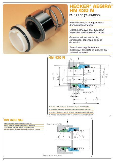
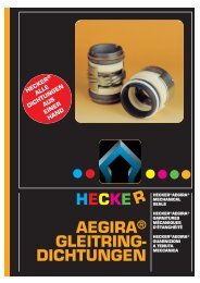
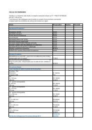
<strong>HECKER</strong> <strong>®</strong> AEGIRA <strong>®</strong> HN 430 N EN 12756 (DIN 24960) Einzel-Gleitringdichtung, entlastet, drehrichtungsabhängig Single mechanical seal, balanced, dependent on direction of rotation Garniture mécanique simple, compensée, dépendant du sens de rotation Guarnizione singola a tenuta meccanica, scaricata, in funzione del senso di rotazione HN 430 N 1) Stellring auf Wunsch unter der Bezeichnung SAE 960/d1 lieferbar 1) Adjusting ring available on request under the designation SAE 960/d1 1) Anneau d’ajustage livrable sur demande sous la désignation SAE 960/d1 1) Collare di spallamento disponibile su richiesta con il numero SAE 960/d1 HN 430 NG Gleitring (Kohle) in Gleitringträger geschrumpft Seal face (carbon) shrink-fitted into rotary seal carrier Grain tournant (carbone) rétracté dans son support Anello scorrevole (in carbone), pressato a caldo nel supporto 8
Konstruktionsmerkmale: Konische Feder zur Drehmomentmitnahme, preisgünstige Dichtung für höhere Drücke Anwendungsbereiche: Chemische Industrie Wasser-, Abwasserpumpen Einsatzgrenzen: p = 25 bar t = – 40°C bis +180°C (bis 120°C bei U1 U1) abhängig vom Werkstoff der Nebenabdichtung v g = 20 m/s (v g = 10 m/s bei U1U1) Standardwerkstoffe: Gleitring: S, A, B, U1 Gegenring: A, B, V, S, U1, Q1, Q2 Weitere Werkstoffe siehe Seite 58 Design features: Conical spring for torque transmission, low-cost seal for higher pressures Fields of application: Chemical industry Water and sewage pumps Application limits: p = 25 bar t = – 40°C to +180°C (up to 120° C for U1 U1) depending on the material of the secondary seal v g = 20 m/s (v g = 10 m/s for U1 U1) Standard materials: Seal face: S, A, B, U1 Stationary ring: A, B, V, S, U1, Q1, Q2 Further materials see page 58 Caractéristiques de construction: Ressort conique vers l’entraîneur de couple, garniture d’un prix avantageux pour des pressions relativement élevées Domaines d’application: Industrie chimique Pompes à eau et `à eaux usées Limites d’utilisation: p = 25 bars t = – 40°C à +180°C (jusqu’à 120°C pour U1 U1) en fonction du matériau du garnissage secondaire v g = 20 m/s (v g = 10 m/s pour U1 U1) Matériaux standard: Grain tournant: S, A, B, U1 Grain fixe: A, B, V, S, U1, Q1, Q2 Voir autres matériaux à la page 59 Caratteristiche costruttive: Molla conica per trascinamento di coppia, guarnizione economica per pressioni maggiori Campi di applicazione: Industria chimica Pompe per erogazione e scarico d’acqua Limiti all’uso: p = 25 bar t = da – 40°C fino a +180°C (fino a 120°C con U1 U1) a seconda del materiale della guarnizione secondaria v g = 20 m/s (v g = 10 m/s con U1 U1) Materiali standard: Anello scorrevole: S, A, B, U1 Anello fisso: A, B, V, S, U1, Q1, Q2 Ulteriori materiali vedere a pagina 59 HN 430 N, HN 430 NG Pos 1 bis 12 DIN Pos. Teile Nr. Benennung 1 472 Gleitring 2 475 Gegenring 3 412.2 Runddichtring 4 412.1 Runddichtring 5 478 Feder rechtsgängig 5 479 Feder linksgängig 6 474 Druckring 11 473 Gleitringträger 12 476 Gegenringträger Maßliste HN 430 N, HN 430 NG Nenn-Ø d 1 012 12 014 14 016 16 018 18 020 20 022 22 024 24 025 25 028 28 030 30 032 32 033 33 035 35 038 38 040 40 043 43 045 45 048 48 050 50 053 53 055 55 058 58 060 60 065 65 d 2 16 18 20 22 24 26 28 30 33 35 38 38 40 43 45 48 50 53 55 58 60 63 65 70 d 3 26 32 34 36 38 40 41 44 47 49 54 54 56 59 61 64 66 69 71 78 80 83 85 90 d 6 19 21 23 27 29 31 33 34 37 39 42 42 44 49 51 54 56 59 62 65 67 70 72 77 d 7 23 25 27 33 35 37 39 40 43 45 48 48 50 56 58 61 63 66 70 73 75 78 80 85 d 8 3 3 3 3 3 3 3 3 3 3 3 3 3 4 4 4 4 4 4 4 4 4 4 4 I 1 ±1 37 38 40 43 45 45 45 46 48 48 50 50 53 60 63 67 67 69 73 76 76 76 76 76 I 1N 50 55 55 55 60 60 60 60 65 65 65 65 65 75 75 75 75 85 85 85 85 85 95 95 I 2 18 18 18 20 20 20 20 20 20 20 20 20 20 23 23 23 23 23 25 25 25 25 25 25 I 3 27 29 30 31,5 33,5 33,5 33,5 34,5 36,5 36,5 38,5 38,5 41,5 47 50 54 54 56 59 62 62 62 62 62 I 5 1,5 1,5 1,5 2 2 2 2 2 2 2 2 2 2 2 2 2 2 2 2,5 2,5 2,5 2,5 2,5 2,5 I 6 4 4 4 5 5 5 5 5 5 5 5 5 5 6 6 6 6 6 6 6 6 6 6 6 I 7+0,5 8,5 8,5 8,5 9 9 9 9 9 9 9 9 9 9 9 9 9 9 9 9 9 9 9 9 9 I 8 13 17 15 12 15 15 15 14 17 17 15 15 12 15 12 8 8 16 12 9 9 9 19 19 Für d 1 >65 empfehlen wir unsere Gleitringdichtung HN 436, Seite 14 For d 1 >65 we recommend our mechanical seal HN 436, page 14 Pour d 1 >65, nous recommandons nos garnitures mécaniques HN 436, page 14 Per d 1 >65 consigliamo l’impiego della nostra guarnizione anulare a tenuta meccanica HN 436, pagina 14 Bestellbeispiel: GLRD HN 430 NG – NB 035 L1 BVVGG (siehe auch Seite 56-59) Example for order: GLRD HN 430 NG – NB 035 L1 BVVGG (please refer also to page 56-59) Exemple de commande: GLRD HN 430 NG – NB 035 L1 BVVGG (voir aussi page 56-59) Esempio di ordinazione: GLRD HN 430 NG – NB 035 L1 BVVGG (ved. anche pagina 56-59) 9