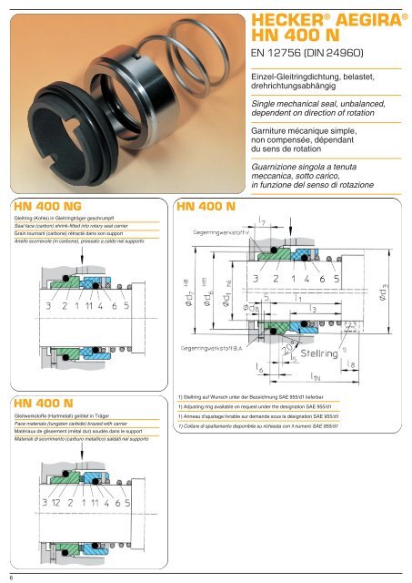
<strong>HECKER</strong> <strong>®</strong> AEGIRA <strong>®</strong> HN 400 N EN 12756 (DIN 24960) Einzel-Gleitringdichtung, belastet, drehrichtungsabhängig Single mechanical seal, unbalanced, dependent on direction of rotation Garniture mécanique simple, non compensée, dépendant du sens de rotation Guarnizione singola a tenuta meccanica, sotto carico, in funzione del senso di rotazione HN 400 NG Gleitring (Kohle) in Gleitringträger geschrumpft Seal face (carbon) shrink-fitted into rotary seal carrier Grain tournant (carbone) rétracté dans son support Anello scorrevole (in carbone), pressato a caldo nel supporto HN 400 N HN 400 N Gleitwerkstoffe (Hartmetall) gelötet in Träger Face materials (tungsten carbide) brazed with carrier Matériaux de glissement (métal dur) soudés dans le support Materiali di scorrimento (carburo metallico) saldati nel supporto 1) Stellring auf Wunsch unter der Bezeichnung SAE 955/d1 lieferbar 1) Adjusting ring available on request under the designation SAE 955/d1 1) Anneau d’ajustage livrable sur demande sous la désignation SAE 955/d1 1) Collare di spallamento disponibile su richiesta con il numero SAE 955/d1 6
Konstruktionsmerkmale: Konische Feder zur Drehmomentmitnahme, preisgünstige Dichtung Anwendungsbereiche: Chemische Industrie Wasser-, Abwasserpumpen Einsatzgrenzen: p = 10 bar t = – 40°C bis +180°C (bis 120°C bei U1U1) abhängig vom Werkstoff der Nebenabdichtung v g = 20 m/s (v g = 10 m/s bei U1U1) Standardwerkstoffe: Gleitring: S, A, B, U1 Gegenring: A, B, V, U1, Q1, Q2 Weitere Werkstoffe siehe Seite 58 Design features: Conical spring for torque transmission, low-cost seal Fields of application: Chemical industry Water and sewage pumps Application limits: p = 10 bar t = – 40°C to +180°C (up to 120° for U1 U1) depending on the material of the secondary seal v g = 20 m/s (v g = 10 m/s for U1 U1) Standard materials: Seal face: S, A, B, U1 stationary ring: A, B, U1, Q1, Q2 Further materials, see page 58 Caractéristiques de construction: Ressort conique vers l’entraîneur de couple, garniture d’un prix avantageux Domaines d’application: Industrie chimique Pompes à eau et à eaux usées Limites d’utilisation: p = 10 bars t = – 40°C à +180°C (jusqu’à 120°C pour U1 U1) en fonction du matériau du garnissage secondaire v g = 20 m/s (v g = 10 m/s pour U1 U1) Matériaux standard: Grain tournant: S, A, B, U1 Grain fixe: A, B, V, U1, Q1, Q2 Voir autres matériaux à la page 59 Caratteristiche costruttive: Molla conica per trascinamento di coppia, guarnizione economica Campi di applicazione: Industria chimica Pompe per erogazione e scarico d’acqua Limiti all’uso: p = 10 bar t = da – 40°C fino a +180°C (fino a 120° con U1 U1) a seconda del materiale, della guarnizione secondaria v g = 20 m/s (v g = 10 m/s con U1 U1) Materiali standard: Anello scorrevole: S, A, B, U1, Anello fisso: A, B, V, U1, Q1, Q2 Ulteriori materiali vedere a pag. 59 HN 400 N, HN 400 NG Pos 1 bis 12 DIN Pos. Teile Nr. Benennung 1 472 Gleitring 2 475 Gegenring 3 412.2 Runddichtring 4 412.1 Runddichtring 5 478 Feder rechtsgängig 5 479 Feder linksgängig 6 474 Druckring 11 473 Gleitringträger 12 476 Gegenringträger Maßliste HN 400 N, HN 400 NG Nenn-Ø 012 014 016 018 020 022 024 025 028 030 032 033 035 038 040 043 045 048 050 053 055 058 060 065 d 1 12 14 16 18 20 22 24 25 28 30 32 33 35 38 40 43 45 48 50 53 55 58 60 65 d 3 21,5 23,5 25,5 30 32 34 36 38 41 43 46 47 49 54 56 59 61 64 66 69 71 78 80 85 d 6 19 21 23 27 29 31 33 34 37 39 42 42 44 49 51 54 56 59 62 65 67 70 72 77 d 7 23 25 27 33 35 37 39 40 43 45 48 48 50 56 58 61 63 66 70 73 75 78 80 85 d 8 3 3 3 3 3 3 3 3 3 3 3 3 3 4 4 4 4 4 4 4 4 4 4 4 I 1 ±1 27,5 27,5 29,5 32 33,5 35 36,5 38 38 38 40 40 40 47,5 50 52,5 55,5 60 60 62 64 70 70 70 I 1N 40 40 40 45 45 45 50 50 50 50 55 55 55 55 55 60 60 60 60 70 70 70 70 80 I 3 ±1 17,5 17,5 19,5 20,5 22 23,5 25 26,5 26,5 26,5 28,5 28,5 28,5 34,5 37 39,5 42,5 47 47 48 50 56 56 56 I 5 1,5 1,5 1,5 2 2 2 2 2 2 2 2 2 2 2 2 2 2 2 2,5 2,5 2,5 2,5 2,5 2,5 I 6 4 4 4 5 5 5 5 5 5 5 5 5 5 6 6 6 6 6 6 6 6 6 6 6 I 7 +0,5 8,5 8,5 8,5 9 9 9 9 9 9 9 9 9 9 9 9 9 9 9 9 9 9 9 9 9 I 8 12,5 12,5 11,5 13 11,5 10 13,5 12 12 12 15 15 15 8 8* 8 8* 8* 8* 8 8* 8* 8* 10 *Maß I 1N wird überschritten. Für d 1 >65 empfehlen wir unsere Gleitringdichtung HN 406, Seite 12 *Dimension I 1N is exceeded. For d 1 >65 we recommend the mechanical seal HN 406, page 12 *Côte I 1N dépassée. Pour d 1 >65, nous recommandons nos garnitures mécaniques HN 406, page 12 *Viene superata la quota I 1N .Per d 1 >65 consigliamo l’impiego della guarnizione anulare a tenuta meccanica HN 406, pagina 12 Bestellbeispiel: GLRD HN 400 N – NU 035 R1 SBVGG (siehe auch Seite 56-59) Example for order: GLRD HN 400 N – NU 035 R1 SBVGG (please refer also to page 56-59) Exemple de commande: GLRD HN 400 N – NU 035 R1 SBVGG (voir aussi page 56-59) Esempio di ordinazione: GLRD HN 400 N – NU 035 R1 SBVGG (ved. anche pagina 56-59) 7