

10-2018
Fachzeitschrift für Hochfrequenz- und Mikrowellentechnik
Fachzeitschrift für Hochfrequenz- und Mikrowellentechnik

Sie wollen auch ein ePaper? Erhöhen Sie die Reichweite Ihrer Titel.
YUMPU macht aus Druck-PDFs automatisch weboptimierte ePaper, die Google liebt.
RF & Wireless<br />
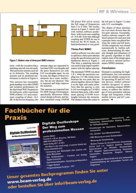
Figure 7: Bottom view of three-port MIMO antenna<br />
(note - with the exception that a<br />
matching network was not used).<br />
This particular antenna used air<br />
as its dielectric. The resulting<br />
antenna and its predicted performance<br />
is shown in Figure 4.<br />
This antenna has reasonably<br />
good standing wave ratio (SWR)<br />
and isolation performance for<br />
the dual-band WiFi frequencies<br />
for both ports, with a maximum<br />
SWR of about 1.8:1 and a maximum<br />
coupling of about -16.5<br />
dB. At the lowest frequency, the<br />
antenna edges are separated by<br />
less than 0.093 wavelengths and<br />
the ports themselves are only<br />
0.41 wavelengths apart. As can<br />
be seen, the shapes of these two<br />
elements have some similarities,<br />
but are not identical. This<br />
is expected and helps improve<br />
the isolation.<br />
This antenna was imported into<br />
NI AWR Design Environment,<br />
specifically Microwave Office<br />
circuit design software, and further<br />
simulated using AXIEM<br />
3D planar EM solver across<br />
the full range of frequencies<br />
from 2 to 6 GHz. The results,<br />
shown in Figure 5, match well<br />
with AntSyn software predictions,<br />
with worst-case coupling<br />
of -16.8 dB. Note that although<br />
coupling and VSWR do rise in<br />
between the Wi-Fi bands, inband<br />
performance is very good.<br />
Three-Port MIMO<br />
AntSyn software was also used<br />
to optimize a three-port antenna<br />
using the specifications and size<br />
limitations shown in Figure 1.<br />
This time, a matching network<br />
was used to help improve performance<br />
with the tighter spacing.<br />
The maximum VSWR was about<br />
1.8:1, while the maximum coupling<br />
was -14.7 dB, which occurs<br />
between the two ports that are<br />
closest together, shown in Figure<br />
6 as the right and center ports.<br />
Note that the spacing is only<br />
0.163 wavelengths (at 2.4 GHz)<br />
between these ports, with a minimum<br />
spacing of 0.048 wavelengths<br />
between the elements.<br />
The distance from the center to<br />
the left port in Figure 7 is also<br />
only 0.31 wavelengths.<br />
The shapes of these antennas<br />
are even more diverse than the<br />
two-port antenna. Essentially,<br />
AntSyn software created a different<br />
antenna for each port and<br />
a parasitic fence was placed between<br />
the center and left ports.<br />
All this complexity was created<br />
automatically by AntSyn software,<br />
demonstrating the inherent<br />
strength and robustness of<br />
the genetic algorithm to fully<br />
explore more of the design space<br />
and produce optimal performance<br />
MIMO antennas.<br />
Conclusion<br />
Demand is escalating for highperformance,<br />
low-cost antennas<br />
to provide reliable connectivity<br />
for upcoming 5G and IoT wireless<br />
devices. AntSyn software<br />
enables designers of antennas,<br />
including compact MIMO<br />
arrays, to address the challenges<br />
of next-generation antenna<br />
design and integration within<br />
mobile devices and IoT components.<br />
◄<br />
Fachbücher für die<br />
Praxis<br />
Digitale Oszilloskope<br />
Der Weg zum<br />
professionellen Messen<br />
Joachim Müller<br />
Format 21 x 28 cm, Broschur, 388 Seiten,<br />
ISBN 978-3-88976-168-2<br />
beam-Verlag 2017, 47,90 €<br />
Ein Blick in den Inhalt zeigt, in welcher Breite das<br />
Thema behandelt wird:<br />
• Verbindung zum Messobjekt über passive und<br />
aktive Messköpfe<br />
• Das Vertikalsystem – Frontend und Analog-<br />
Digital-Converter<br />
• Das Horizontalsystem – Sampling und Akquisition<br />
• Trigger-System<br />
• Frequenzanalyse-Funktion – FFT<br />
Unser gesamtes Buchprogramm finden Sie unter<br />
www.beam-verlag.de<br />
oder bestellen Sie über info@beam-verlag.de<br />
• Praxis-Demonstationen: Untersuchung von<br />
Taktsignalen, Demonstration Aliasing, Einfluss<br />
der Tastkopfimpedanz<br />
• Einstellungen der Dezimation, Rekonstruktion,<br />
Interpolation<br />
• Die „Sünden“ beim Masseanschluss<br />
• EMV-Messung an einem Schaltnetzteil<br />
• Messung der Kanalleistung<br />
Weitere Themen für die praktischen Anwendungs-<br />
Demos sind u.a.: Abgleich passiver Tastköpfe,<br />
Demonstration der Blindzeit, Demonstration<br />
FFT, Ratgeber Spektrumdarstellung, Dezimation,<br />
Interpolation, Samplerate, Ratgeber: Gekonnt<br />
triggern.<br />
Im Anhang des Werks findet sich eine umfassende<br />
Zusammenstellung der verwendeten Formeln und<br />
Diagramme.<br />
hf-praxis <strong>10</strong>/<strong>2018</strong> 79


