

10-2018
Fachzeitschrift für Hochfrequenz- und Mikrowellentechnik
Fachzeitschrift für Hochfrequenz- und Mikrowellentechnik

Sie wollen auch ein ePaper? Erhöhen Sie die Reichweite Ihrer Titel.
YUMPU macht aus Druck-PDFs automatisch weboptimierte ePaper, die Google liebt.
RF & Wireless<br />
UPCT Students Design a Ku-Band Multiplexer<br />
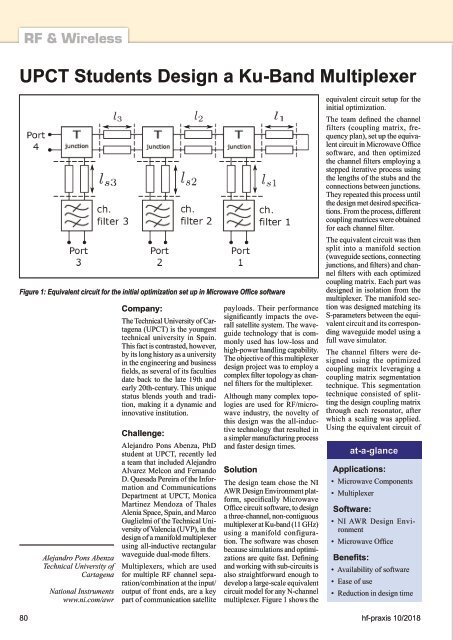
Figure 1: Equivalent circuit for the initial optimization set up in Microwave Office software<br />
Alejandro Pons Abenza<br />
Technical University of<br />
Cartagena<br />
National Instruments<br />
www.ni.com/awr<br />
Company:<br />
The Technical University of Cartagena<br />
(UPCT) is the youngest<br />
technical university in Spain.<br />
This fact is contrasted, however,<br />
by its long history as a university<br />
in the engineering and business<br />
fields, as several of its faculties<br />
date back to the late 19th and<br />
early 20th-century. This unique<br />
status blends youth and tradition,<br />
making it a dynamic and<br />
innovative institution.<br />
Challenge:<br />
Alejandro Pons Abenza, PhD<br />
student at UPCT, recently led<br />
a team that included Alejandro<br />
Alvarez Melcon and Fernando<br />
D. Quesada Pereira of the Information<br />
and Communications<br />
Department at UPCT, Monica<br />
Martinez Mendoza of Thales<br />
Alenia Space, Spain, and Marco<br />
Guglielmi of the Technical University<br />
of Valencia (UVP), in the<br />
design of a manifold multiplexer<br />
using all-inductive rectangular<br />
waveguide dual-mode filters.<br />
Multiplexers, which are used<br />
for multiple RF channel separation/combination<br />
at the input/<br />
output of front ends, are a key<br />
part of communication satellite<br />
payloads. Their performance<br />
significantly impacts the overall<br />
satellite system. The waveguide<br />
technology that is commonly<br />
used has low-loss and<br />
high-power handling capability.<br />
The objective of this multiplexer<br />
design project was to employ a<br />
complex filter topology as channel<br />
filters for the multiplexer.<br />
Although many complex topologies<br />
are used for RF/microwave<br />
industry, the novelty of<br />
this design was the all-inductive<br />
technology that resulted in<br />
a simpler manufacturing process<br />
and faster design times.<br />
Solution<br />
The design team chose the NI<br />
AWR Design Environment platform,<br />
specifically Microwave<br />
Office circuit software, to design<br />
a three-channel, non-contiguous<br />
multiplexer at Ku-band (11 GHz)<br />
using a manifold configuration.<br />
The software was chosen<br />
because simulations and optimizations<br />
are quite fast. Defining<br />
and working with sub-circuits is<br />
also straightforward enough to<br />
develop a large-scale equivalent<br />
circuit model for any N-channel<br />
multiplexer. Figure 1 shows the<br />
equivalent circuit setup for the<br />
initial optimization.<br />
The team defined the channel<br />
filters (coupling matrix, frequency<br />
plan), set up the equivalent<br />
circuit in Microwave Office<br />
software, and then optimized<br />
the channel filters employing a<br />
stepped iterative process using<br />
the lengths of the stubs and the<br />
connections between junctions.<br />
They repeated this process until<br />
the design met desired specifications.<br />
From the process, different<br />
coupling matrices were obtained<br />
for each channel filter.<br />
The equivalent circuit was then<br />
split into a manifold section<br />
(waveguide sections, connecting<br />
junctions, and filters) and channel<br />
filters with each optimized<br />
coupling matrix. Each part was<br />
designed in isolation from the<br />
multiplexer. The manifold section<br />
was designed matching its<br />
S-parameters between the equivalent<br />
circuit and its corresponding<br />
waveguide model using a<br />
full wave simulator.<br />
The channel filters were designed<br />
using the optimized<br />
coupling matrix leveraging a<br />
coupling matrix segmentation<br />
technique. This segmentation<br />
technique consisted of splitting<br />
the design coupling matrix<br />
through each resonator, after<br />
which a scaling was applied.<br />
Using the equivalent circuit of<br />
at-a-glance<br />
Applications:<br />
• Microwave Components<br />
• Multiplexer<br />
Software:<br />
• NI AWR Design Environment<br />
• Microwave Office<br />
Benefits:<br />
• Availability of software<br />
• Ease of use<br />
• Reduction in design time<br />
80 hf-praxis <strong>10</strong>/<strong>2018</strong>


