DRAFT Recommended Practice for Measurements and ...
DRAFT Recommended Practice for Measurements and ...
DRAFT Recommended Practice for Measurements and ...

Create successful ePaper yourself
Turn your PDF publications into a flip-book with our unique Google optimized e-Paper software.
1/29/98 106 C95.3-1991 Revision — 2 nd Draft<br />
10/98 Draft<br />
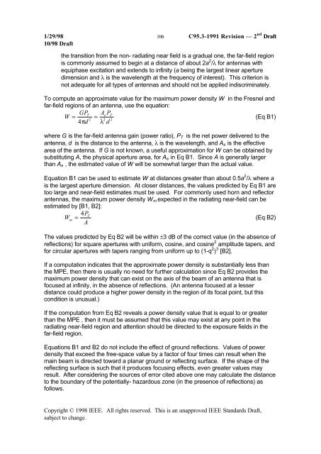
the transition from the non- radiating near field is a gradual one, the far-field region<br />
is commonly assumed to begin at a distance of about 2a 2 /λ <strong>for</strong> antennas with<br />
equiphase excitation <strong>and</strong> extends to infinity (a being the largest linear aperture<br />
dimension <strong>and</strong> λ is the wavelength at the frequency of interest). This criterion is<br />
not adequate <strong>for</strong> all types of antennas <strong>and</strong> should not be applied indiscriminately.<br />
To compute an approximate value <strong>for</strong> the maximum power density W in the Fresnel <strong>and</strong><br />
far-field regions of an antenna, use the equation:<br />
W<br />
GP T<br />
Ae PT<br />
= =<br />
(Eq B1)<br />
2 2 2<br />
4πd<br />
λ d<br />
where G is the far-field antenna gain (power ratio), P T is the net power delivered to the<br />
antenna, d is the distance to the antenna, λ is the wavelength, <strong>and</strong> A e is the effective<br />
area of the antenna. If G is not known, a useful approximation <strong>for</strong> W can be obtained by<br />
substituting A, the physical aperture area, <strong>for</strong> A e in Eq B1. Since A is generally larger<br />
than A e , the estimated value of W will be somewhat larger than the actual value.<br />
Equation B1 can be used to estimate W at distances greater than about 0.5a 2 /λ where a<br />
is the largest aperture dimension. At closer distances, the values predicted by Eq B1 are<br />
too large <strong>and</strong> near-field estimates must be used. For commonly used horn <strong>and</strong> reflector<br />
antennas, the maximum power density W m expected in the radiating near-field can be<br />
estimated by [B1, B2]:<br />
PT<br />
Wm<br />
= 4 (Eq B2)<br />
A<br />
The values predicted by Eq B2 will be within ±3 dB of the correct value (in the absence of<br />
reflections) <strong>for</strong> square apertures with uni<strong>for</strong>m, cosine, <strong>and</strong> cosine 2 amplitude tapers, <strong>and</strong><br />
<strong>for</strong> circular apertures with tapers ranging from uni<strong>for</strong>m up to (1-q 2 ) 3 [B2].<br />
If a computation indicates that the approximate power density is substantially less than<br />
the MPE, then there is usually no need <strong>for</strong> further calculation since Eq B2 provides the<br />
maximum power density that can exist on the axis of the beam of an antenna that is<br />
focused at infinity, in the absence of reflections. (An antenna focused at a lesser<br />
distance could produce a higher power density in the region of its focal point, but this<br />
condition is unusual.)<br />
If the computation from Eq B2 reveals a power density value that is equal to or greater<br />
than the MPE , then it must be assumed that this value may exist at any point in the<br />
radiating near-field region <strong>and</strong> attention should be directed to the exposure fields in the<br />
far-field region.<br />
Equations B1 <strong>and</strong> B2 do not include the effect of ground reflections. Values of power<br />
density that exceed the free-space value by a factor of four times can result when the<br />
main beam is directed toward a planar ground or reflecting surface. If the shape of the<br />
reflecting surface is such that it produces focusing effects, even greater values may<br />
result. After considering the sources of error cited above one may calculate the distance<br />
to the boundary of the potentially- hazardous zone (in the presence of reflections) as<br />
follows.<br />
Copyright © 1998 IEEE. All rights reserved. This is an unapproved IEEE St<strong>and</strong>ards Draft,<br />
subject to change.