DRAFT Recommended Practice for Measurements and ...
DRAFT Recommended Practice for Measurements and ...
DRAFT Recommended Practice for Measurements and ...

You also want an ePaper? Increase the reach of your titles
YUMPU automatically turns print PDFs into web optimized ePapers that Google loves.
1/29/98 128 C95.3-1991 Revision — 2 nd Draft<br />
10/98 Draft<br />
D6. Theoretical Considerations <strong>for</strong> the Determination of SAR Associated with<br />
Near-Field Exposures<br />
The results of detailed mathematical analyses of the SAR distribution at different points<br />
within a person's body, due to exposure to near-field sources, aid in estimating the order<br />
of magnitude of the corresponding induced SAR. The corresponding exposure may or<br />
may not be in the reactive near field of a radiator. The following considerations can aid<br />
estimating the type of exposure (near- or far-field), <strong>and</strong> in the subsequent assessment of<br />
the feasibility of estimating the internal SAR distributions in exposed personnel.<br />
D6.1 Theoretical Considerations <strong>for</strong> Estimating RF Coupling <strong>and</strong> SAR<br />
Associated with Reactive Near-Field Exposure.<br />
Either reduced or enhanced absorption situations exist (see 5.6) <strong>for</strong> personnel exposed<br />
to nonradiating, reactive near fields of a nearby source. One principal factor that<br />
determines the relative magnitude of the induced SAR is the type <strong>and</strong> degree of coupling<br />
between the RF source (an active radiator or passive radiator) <strong>and</strong> the exposed object.<br />
For the case where the distance between the object (person) <strong>and</strong> the source is much<br />
less than one wavelength, E <strong>and</strong> H exhibit a rapid decrease in amplitude with increasing<br />
separation distance.<br />
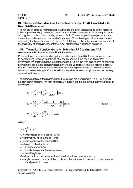
The characteristics of the reactive near-field region are described in 3.1.4. For a small<br />
electric dipole antenna, the field strength at a point r can be expressed mathematically as<br />
follows [D17]:<br />
E<br />
E<br />
H<br />
r<br />
θ<br />
φ<br />
I0h e<br />
− jkr ⎛ 2η<br />
2<br />
= ⎜ +<br />
4π<br />
⎝ d jωεd<br />
2 3<br />
⎞<br />
⎟ cosθ<br />
⎠<br />
I0h j e<br />
− jkr⎛<br />
ωµ 1 η ⎞<br />
= ⎜ + + ⎟ sin θ<br />
(Eq D11 )<br />
3 2<br />
4π<br />
⎝ d jωd d ⎠<br />
I0h jk e<br />
− jkr<br />
=<br />
⎛ 1<br />
⎜ +<br />
⎞<br />
⎟ θ<br />
π ⎝<br />
2 sin<br />
4 d d ⎠<br />
where:<br />
k = 2π λ<br />
(1/m)<br />
η = impedance of free space (377 Ω)<br />
ε = permittivity of free space (F/m)<br />
µ = permeability of free space (H/m)<br />
h = length of the dipole (m)<br />
I o = antenna current (A)<br />
ω = angular frequency (radians/second)<br />
λ = wavelength (m)<br />
d = distance from the center of the dipole to the location of interest (m)<br />
θ = angle between the axis of the dipole <strong>and</strong> the unit direction vector from the center of<br />
the dipole to the point r.<br />
Copyright © 1998 IEEE. All rights reserved. This is an unapproved IEEE St<strong>and</strong>ards Draft,<br />
subject to change.