DRAFT Recommended Practice for Measurements and ...
DRAFT Recommended Practice for Measurements and ...
DRAFT Recommended Practice for Measurements and ...
You also want an ePaper? Increase the reach of your titles
YUMPU automatically turns print PDFs into web optimized ePapers that Google loves.
1/29/98 52 C95.3-1991 Revision — 2 nd Draft<br />
10/98 Draft<br />
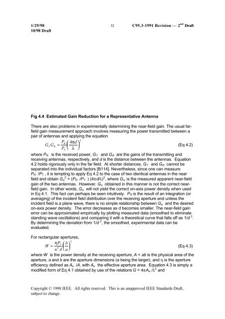
Fig 4.4 Estimated Gain Reduction <strong>for</strong> a Representative Antenna<br />
There are also problems in experimentally determining the near-field gain. The usual farfield<br />
gain measurement approach involves measuring the power transmitted between a<br />
pair of antennas <strong>and</strong> applying the equation<br />
G G<br />
T<br />
R<br />
PR<br />
=<br />
P<br />
T<br />
⎛<br />
⎜<br />
⎝<br />
4πd⎞<br />
⎟<br />
λ ⎠<br />
2<br />
(Eq 4.2)<br />
where P R is the received power, G T <strong>and</strong> G R are the gains of the transmitting <strong>and</strong><br />
receiving antennas, respectively, <strong>and</strong> d is the distance between the antennas. Equation<br />
4.2 holds rigorously only in the far field. At shorter distances, G T <strong>and</strong> G R cannot be<br />
separated into the individual factors [B114]. Nevertheless, since one can measure<br />
P R /P T , it is tempting to apply Eq 4.2 to the case of two identical antennas in the near<br />
field <strong>and</strong> obtain G a 2 = (P R /P T ) (4πd/λ) 2 , where G a is the measured apparent near-field<br />
gain of the two antennas. However, G a obtained in this manner is not the correct nearfield<br />
gain. In other words, G a will not yield the correct on-axis power density when used<br />
in Eq 4.1. This fact can perhaps be seen intuitively. P R is the result of an integration (or<br />
averaging) of the incident field distribution over the receiving aperture <strong>and</strong> unless the<br />
incident field is a plane wave, there is no simple relationship between G a <strong>and</strong> the desired<br />
on-axis power density. The error decreases as d becomes smaller. The near-field gain<br />
error can be approximated empirically by plotting measured data (smoothed to eliminate<br />
st<strong>and</strong>ing wave oscillations) <strong>and</strong> comparing it with a theoretical curve that falls off as 1/d 2 .<br />
By determining the deviation from 1/d 2 , the smoothed, experimental data can be<br />
evaluated.<br />
For rectangular apertures,<br />
PT<br />
⎛ b<br />
W = ⎜ ⎞ 2<br />
η<br />
n A ⎝ a⎠ ⎟<br />
(Eq 4.3)<br />
2<br />
where W is the power density at the receiving aperture, A = ab is the physical area of the<br />
aperture, a <strong>and</strong> b are the aperture dimensions (a being the larger), <strong>and</strong> η is the aperture<br />
efficiency defined as A e /A, with A e the effective aperture area. Equation 4.3 is simply a<br />
modified <strong>for</strong>m of Eq 4.1 obtained by use of the relations G = 4πA e /λ 2 <strong>and</strong><br />
Copyright © 1998 IEEE. All rights reserved. This is an unapproved IEEE St<strong>and</strong>ards Draft,<br />
subject to change.


