DRAFT Recommended Practice for Measurements and ...
DRAFT Recommended Practice for Measurements and ...
DRAFT Recommended Practice for Measurements and ...

Create successful ePaper yourself
Turn your PDF publications into a flip-book with our unique Google optimized e-Paper software.
1/29/98 59 C95.3-1991 Revision — 2 nd Draft<br />
10/98 Draft<br />
termination at frequencies up to about 30 MHz. When the cell is open-circuited, it acts as<br />
a parallel plate capacitor rather than a transmission line, <strong>and</strong> produces a field with a high<br />
intrinsic impedance (high E/H ratio). Large E-fields can then be produced by connecting<br />
a broadb<strong>and</strong> step-up trans<strong>for</strong>mer at the cell input terminal. By contrast, when the cell is<br />
short-circuited it acts as a single turn loop <strong>and</strong> produces a field having a very low intrinsic<br />
impedance. This configuration is useful <strong>for</strong> producing large H-fields.<br />
4.5.3.6 Wideb<strong>and</strong> TEM Cells. If a TEM cell is ''loaded'' in strategic locations with<br />
microwave absorbing material (such as the carbon-filled foam that is used in anechoic<br />
chambers), higher-order modes can be suppressed. The resulting cell can there<strong>for</strong>e<br />
generate a calculable, relatively pure TEM mode, at frequencies that are much higher<br />
than would be possible using st<strong>and</strong>ard TEM cells [B35]. This condition degenerates<br />
whenever reflecting (metallic or dielectric) objects are introduced in the cell. For<br />
calibrating probes with very small sensors <strong>and</strong> nonperturbing leads (resistive or fiber<br />
optics), specially designed absorber-loaded TEM cells may be useful over a very broad<br />
range of frequencies (DC-18 GHz) [B83]. Careful design, testing, <strong>and</strong> error-analysis<br />
should be per<strong>for</strong>med <strong>for</strong> each specific combination of TEM cell <strong>and</strong> sensor under test, to<br />
ensure reasonable per<strong>for</strong>mance at any frequency in the range where undesirable higherorder<br />
modes may exist.<br />
4.5.4 Magnetic Field Generators Using Coils.<br />
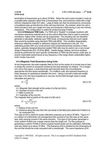
At low frequencies, the axial magnetic field (in A/m) at the center of a circular loop of wire<br />
is simply the current (in amperes) divided by the loop diameter (in meters). For a singleturn<br />
coil in free space, a loop becomes self-resonant when the circumference<br />
approaches the free space wavelength. For multiturn coils, the resonant frequency is<br />
lower because of capacitance between the turns. Using a coil with a total wire length<br />
less than λ/10, the input impedance is very low, but the field strength value is easily<br />
calculable <strong>and</strong> given by<br />
H<br />
= NI<br />
(Eq 4.13)<br />
D<br />
where:<br />
H = Magnetic field strength at the center of a flat coil (A/m),<br />
N = Number of turns in the coil<br />
I = RMS Current (A)<br />
D = Diameter of the coil (m).<br />
The magnetic field at points on the axis of a flat coil is<br />
2<br />
NIr<br />
H =<br />
(Eq 4.14)<br />
2 2 3 2<br />
2( r + d ) /<br />
where:<br />
r = Radius of the coil (m)<br />
d = Distance along the axis from the coil center to the field point where the H-field is to<br />
be computed (m)<br />
This type of coil is useful <strong>for</strong> probe calibration purposes up to about 30 MHz. Figure 4.7<br />
is a sketch of a Helmholtz coil arrangement that consists of two flat coils on the same<br />
axis, both carrying current in the same direction. This type of coil system generates a<br />
more uni<strong>for</strong>m H-field over a larger volume than the single coil. For the purpose of<br />
generating a uni<strong>for</strong>m H-field in which a typical hazard probe can be calibrated, Helmholtz<br />
coils are useful up to about 10 MHz. This frequency limit is dictated by the dimensions of<br />
the coil that should be small compared with a wavelength. The wave impedance (E/H<br />
Copyright © 1998 IEEE. All rights reserved. This is an unapproved IEEE St<strong>and</strong>ards Draft,<br />
subject to change.