DRAFT Recommended Practice for Measurements and ...
DRAFT Recommended Practice for Measurements and ...
DRAFT Recommended Practice for Measurements and ...

You also want an ePaper? Increase the reach of your titles
YUMPU automatically turns print PDFs into web optimized ePapers that Google loves.
1/29/98 57 C95.3-1991 Revision — 2 nd Draft<br />
10/98 Draft<br />
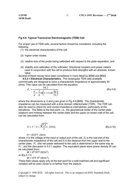
Fig 4.6 Typical Transverse Electromagnetic (TEM) Cell<br />
For proper use of TEM cells, several factors should be considered, including the<br />
following:<br />
(1) the electrical characteristics of the cell<br />
(2) higher order modes<br />
(3) relative size of the probe being calibrated with respect to the plate separation, <strong>and</strong><br />
(4) stability <strong>and</strong> calibration of the voltmeter, directional couplers <strong>and</strong> power meters<br />
used in conjunction with the cell to produce field strengths with an absolute, known<br />
value.<br />
Several of these issues have been considered in more detail by [B58] <strong>and</strong> [B90].<br />
4.5.3.1 Electrical Characteristics. The rectangular TEM cells available<br />
commercially are designed to have a characteristic impedance of approximately 50<br />
ohms. This value can be calculated from the equation:<br />
94.<br />
2<br />
Zo =<br />
w<br />
+<br />
⎛<br />
⎜ + Coth<br />
g (Eq 4.9)<br />
2 π<br />
ln 1<br />
⎞<br />
⎟<br />
d π ⎝ 2b⎠<br />
where the dimensions w, b <strong>and</strong> g are given in Fig 4.6 [B89]. The characteristic<br />
impedance can be measured with a time domain reflectometer (TDR). The TDR can<br />
also be used to check <strong>for</strong> <strong>and</strong> correct impedance mismatches, particularly at the<br />
transitions. The fields at the test point, i.e., the geometrical center of the center plate<br />
(septum) <strong>and</strong> midway between the center plate <strong>and</strong> the upper (or lower) wall of the cell,<br />
can be calculated from:<br />
Pn<br />
Zo<br />
E = V / b = (V/m) (Eq 4.10)<br />
b<br />
H = E/377 (A/m)<br />
where V is the voltage at the input or output port of the cell, Z 0 is the real part of the<br />
characteristic impedance of the cell <strong>and</strong> b is the distance from the upper wall to the<br />
center plate. P n (the net power delivered to the cell) is determined in the same way as<br />
P T , <strong>and</strong> the discussion in 4.5.1 applies. The equivalent plane wave power density W can<br />
be calculated from:<br />
W = E 2 /377 (W/m 2 )<br />
or (Eq 4.11)<br />
W = 377 H 2 (W/m 2 )<br />
These field values apply only at the test point <strong>for</strong> a well-matched cell <strong>and</strong> significant<br />
variation will be seen closer to or farther from the septum.<br />
Copyright © 1998 IEEE. All rights reserved. This is an unapproved IEEE St<strong>and</strong>ards Draft,<br />
subject to change.