

NetSure ITM Installation Manual - Gruber Power
NetSure ITM Installation Manual - Gruber Power
NetSure ITM Installation Manual - Gruber Power

Create successful ePaper yourself
Turn your PDF publications into a flip-book with our unique Google optimized e-Paper software.
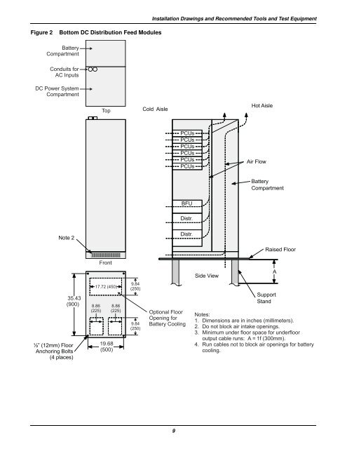
<strong>Installation</strong> Drawings and Recommended Tools and Test Equipment<br />
Figure 2<br />
Bottom DC Distribution Feed Modules<br />
Battery<br />
Compartment<br />
Conduits for<br />
AC Inputs<br />
DC <strong>Power</strong> System<br />
Compartment<br />
Top<br />
Cold Aisle<br />
HotAisle<br />
PCUs<br />
PCUs<br />
PCUs<br />
PCUs<br />
PCUs<br />
PCUs<br />
AirFlow<br />
Battery<br />
Compartment<br />
BFU<br />
Distr.<br />
Note2<br />
Distr.<br />
35.43<br />
(900)<br />
½” (12mm) Floor<br />
Anchoring Bolts<br />
(4 places)<br />
Front<br />
17.72 (450)<br />
8.86<br />
(225)<br />
19.68<br />
(500)<br />
9.84<br />
(250)<br />
8.86<br />
(225) Optional Floor<br />
9.84<br />
(250)<br />
Opening for<br />
Battery Cooling<br />
Side View<br />
Raised Floor<br />
A<br />
Support<br />
Stand<br />
Notes:<br />
1. Dimensions areininches (millimeters).<br />
2. Do not block airintake openings.<br />
3. Minimum under floor space for underfloor<br />
output cable runs: A=1f (300mm).<br />
4. Run cables not to block air openings for battery<br />
cooling.<br />
9


