PhD Fekete - SZIE version - 2.2 - Szent István Egyetem
PhD Fekete - SZIE version - 2.2 - Szent István Egyetem
PhD Fekete - SZIE version - 2.2 - Szent István Egyetem

You also want an ePaper? Increase the reach of your titles
YUMPU automatically turns print PDFs into web optimized ePapers that Google loves.
Materials and Methods<br />
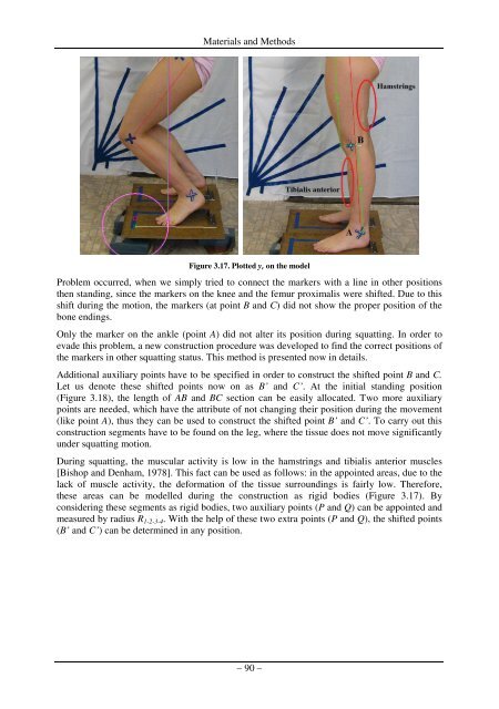
Figure 3.17. Plotted y c on the model<br />
Problem occurred, when we simply tried to connect the markers with a line in other positions<br />
then standing, since the markers on the knee and the femur proximalis were shifted. Due to this<br />
shift during the motion, the markers (at point B and C) did not show the proper position of the<br />
bone endings.<br />
Only the marker on the ankle (point A) did not alter its position during squatting. In order to<br />
evade this problem, a new construction procedure was developed to find the correct positions of<br />
the markers in other squatting status. This method is presented now in details.<br />
Additional auxiliary points have to be specified in order to construct the shifted point B and C.<br />
Let us denote these shifted points now on as B’ and C’. At the initial standing position<br />
(Figure 3.18), the length of AB and BC section can be easily allocated. Two more auxiliary<br />
points are needed, which have the attribute of not changing their position during the movement<br />
(like point A), thus they can be used to construct the shifted point B’ and C’. To carry out this<br />
construction segments have to be found on the leg, where the tissue does not move significantly<br />
under squatting motion.<br />
During squatting, the muscular activity is low in the hamstrings and tibialis anterior muscles<br />
[Bishop and Denham, 1978]. This fact can be used as follows: in the appointed areas, due to the<br />
lack of muscle activity, the deformation of the tissue surroundings is fairly low. Therefore,<br />
these areas can be modelled during the construction as rigid bodies (Figure 3.17). By<br />
considering these segments as rigid bodies, two auxiliary points (P and Q) can be appointed and<br />
measured by radius R 1-2-3-4 . With the help of these two extra points (P and Q), the shifted points<br />
(B’ and C’) can be determined in any position.<br />
– 90 –