PDF 1.938kB
PDF 1.938kB
PDF 1.938kB

You also want an ePaper? Increase the reach of your titles
YUMPU automatically turns print PDFs into web optimized ePapers that Google loves.
4.3. ABSTRACT SYSTEM DESCRIPTION 27<br />
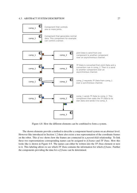
comp_1<br />
Component that controls<br />
one or more joints.<br />
comp_1<br />
Component that generates normal<br />
data. This component for example<br />
can control a sensor.<br />
comp_1<br />
comp_2<br />
Joint Data is send from one<br />
component to another component<br />
over an asynchronous channel.<br />
comp_1<br />
comp_2<br />
TF Data is converted from Joint Data and a<br />
convertion rule in comp_1. Then it is send<br />
to another component over an<br />
asynchronous channel.<br />
comp_1<br />
comp_2<br />
comp_2 requests TF Data from comp_1<br />
over a synchronous channel.<br />
comp_1<br />
comp_2<br />
comp_1 sends TF Data to comp_2. This<br />
component then adds the TF Data to its<br />
own data and sends it to comp_3.<br />
comp_3<br />
Figure 4.8: How the different elements can be combined to form a system.<br />
The shown elements provide a method to describe a component-based system on an abstract level.<br />
However like introduced in Section 1.2 there also exists a tree representation of the coordinate frames<br />
on the robot. This tf tree shows how the frames are connected in a parent/child relationship. To link<br />
these two representations corresponding names can be assigned to tf frames and TF Data. How this<br />
looks like is shown in Figure 4.9. The names can either be written into the TF Data element or next<br />
to it. This labeling allows to see which TF Data contains the information for which tf frame. Further<br />
the components providing the data for a tf frame can be determined.