PDF 1.938kB
PDF 1.938kB
PDF 1.938kB

Create successful ePaper yourself
Turn your PDF publications into a flip-book with our unique Google optimized e-Paper software.
4.6. CONSTRUCTING TF SYSTEMS 43<br />
1.8<br />
1.6<br />
1.4<br />
1.2<br />
1<br />
0.8<br />
0.6<br />
0.4<br />
0.2<br />
0<br />
−0.2<br />
0 0.5 1 1.5 2 2.5 3 3.5 4 4.5<br />
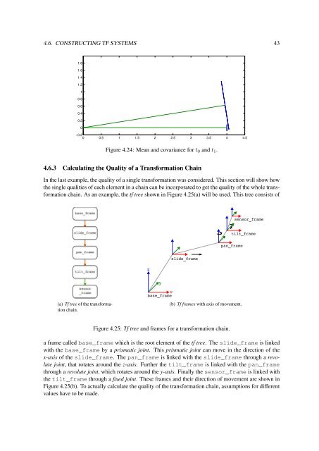
Figure 4.24: Mean and covariance for t 0 and t 1 .<br />
4.6.3 Calculating the Quality of a Transformation Chain<br />
In the last example, the quality of a single transformation was considered. This section will show how<br />
the single qualities of each element in a chain can be incorporated to get the quality of the whole transformation<br />
chain. As an example, the tf tree shown in Figure 4.25(a) will be used. This tree consists of<br />
sensor_frame<br />
tilt_frame<br />
pan_frame<br />
z<br />
slide_frame<br />
y<br />
(a) Tf tree of the transformation<br />
chain.<br />
x<br />
base_frame<br />
(b) Tf frames with axis of movement.<br />
Figure 4.25: Tf tree and frames for a transformation chain.<br />
a frame called base_frame which is the root element of the tf tree. The slide_frame is linked<br />
with the base_frame by a prismatic joint. This prismatic joint can move in the direction of the<br />
x-axis of the slide_frame. The pan_frame is linked with the slide_frame through a revolute<br />
joint, that rotates around the z-axis. Further the tilt_frame is linked with the pan_frame<br />
through a revolute joint, which rotates around the y-axis. Finally the sensor_frame is linked with<br />
the tilt_frame through a fixed joint. These frames and their direction of movement are shown in<br />
Figure 4.25(b). To actually calculate the quality of the transformation chain, assumptions for different<br />
values have to be made.