PDF 1.938kB
PDF 1.938kB
PDF 1.938kB

Create successful ePaper yourself
Turn your PDF publications into a flip-book with our unique Google optimized e-Paper software.
4.6. CONSTRUCTING TF SYSTEMS 39<br />
validity of TF Data was introduced. Three values, namely the point in time t at which the TF Data was<br />
captured, the period of time t valid how long the TF Data is valid and the type of the transformation<br />
have to be added. Since the timestamp needed for the quality measurement is equal to t, the only<br />
values that have to be added are t valid and the type of the transformation.<br />
All the values described until now define the Communication Object which in pseudo code could<br />
look like shown in Listing 4.1.<br />
float64 x, y ,z<br />
float64 q0, q1, q2, q3<br />
Listing 4.1: Values for the Communication Object<br />
# 3D vector<br />
# Quaternion<br />
string parent_frame<br />
string current_frame<br />
uint32 seq_id<br />
# name of the parent frame<br />
# name of the current frame<br />
# optional sequence number<br />
time timestamp<br />
float64[] state_vector<br />
float64[][] covariance_matrix<br />
enum joint_type<br />
float64 jx, jy, jz<br />
# time when TF Data was captured<br />
# state vector of size n<br />
# covariance matrix of size n x n<br />
# type of the joint<br />
# 3D vector specifying joint axis<br />
time time_valid<br />
enum frame_type<br />
# period of time, the data is valid<br />
# dynamic (fixed/moving) or static frame<br />
4.6 Constructing TF Systems<br />
4.6.1 System Modelling<br />
In this section some real world examples with the elements described in Section 4.3 will be presented.<br />
These examples show that the introduced elements allow to model any kind of system, since they<br />
provide a representation for any relevant element of the system.<br />
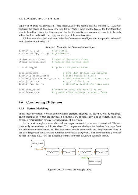
For the next examples a setup where a laser ranger is mounted on an arm is considered. The arm<br />
is statically mounted on a mobile robot base. The components which are involved are base, arm, laser<br />
and another component named xy. The latter component is interested in the transformation chain of<br />
the laser ranger and the laser scan published by the laser component. The corresponding tf tree can<br />
be seen in Figure 4.20. First the modelling of this setup with the ROS tf system is shown.<br />
dynamic<br />
static<br />
Figure 4.20: TF tree for the example setup.